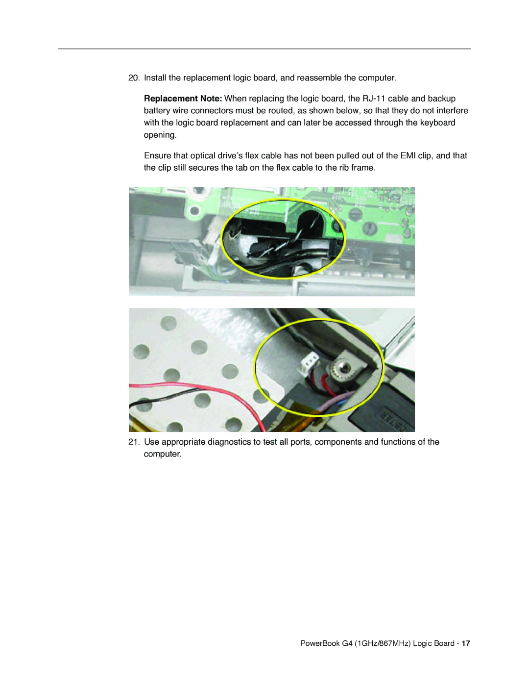
20.Install the replacement logic board, and reassemble the computer.
Replacement Note: When replacing the logic board, the
Ensure that optical drive’s flex cable has not been pulled out of the EMI clip, and that the clip still secures the tab on the flex cable to the rib frame.
21.Use appropriate diagnostics to test all ports, components and functions of the computer.
