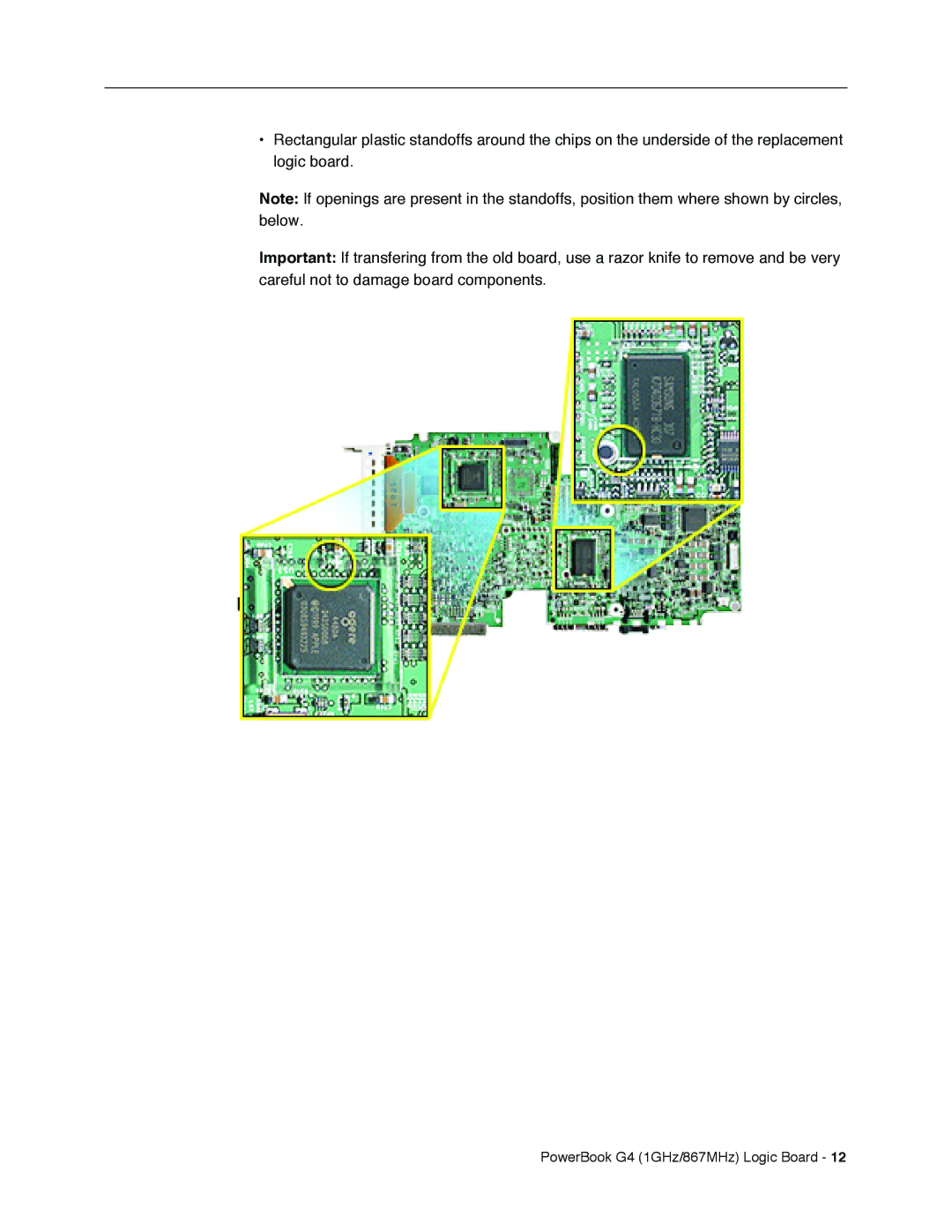
•Rectangular plastic standoffs around the chips on the underside of the replacement logic board.
Note: If openings are present in the standoffs, position them where shown by circles, below.
Important: If transfering from the old board, use a razor knife to remove and be very careful not to damage board components.