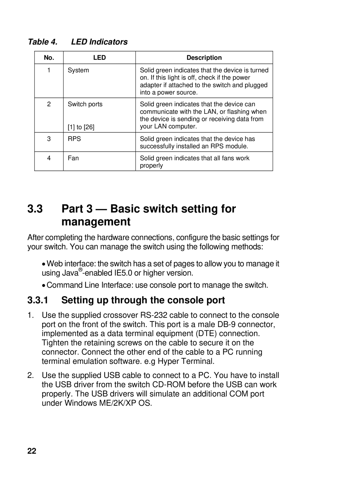
Table 4. | LED Indicators |
| |
|
|
|
|
| No. | LED | Description |
|
|
|
|
| 1 | System | Solid green indicates that the device is turned |
|
|
| on. If this light is off, check if the power |
|
|
| adapter if attached to the switch and plugged |
|
|
| into a power source. |
| 2 | Switch ports | Solid green indicates that the device can |
|
|
| communicate with the LAN, or flashing when |
|
|
| the device is sending or receiving data from |
|
| [1] to [26] | your LAN computer. |
|
|
|
|
| 3 | RPS | Solid green indicates that the device has |
|
|
| successfully installed an RPS module. |
| 4 | Fan | Solid green indicates that all fans work |
|
|
| properly |
3.3Part 3 — Basic switch setting for management
After completing the hardware connections, configure the basic settings for your switch. You can manage the switch using the following methods:
•Web interface: the switch has a set of pages to allow you to manage it using
•Command Line Interface: use console port to manage the switch.
3.3.1Setting up through the console port
1.Use the supplied crossover
Tighten the retaining screws on the cable to secure it on the connector. Connect the other end of the cable to a PC running terminal emulation software. e.g Hyper Terminal.
2.Use the supplied USB cable to connect to a PC. You have to install the USB driver from the switch
22