Chapter 4 | Installation |
|
|
To connect stacked switches:
Note: When adding a module to an existing stack, first connect the stacking cables and then power up the module.
1Plug the light grey connector of the Short Octaplane cable into the port marked “to upper unit” of the bottom P330 Family module.
2Plug dark grey connector of same Short Octaplane cable to the port marked “to lower unit” in the unit above. The connections are illustrated in Figure 4.3.
3Repeat Steps 1 and 2 until you reach the top switch in the stack.
4If you wish to implement stack redundancy, use the Redundant Cable to connect the port marked “ to lower unit” on the bottom switch to the port marked “to upper unit” on top switch of the stack.
5Power up the added modules.
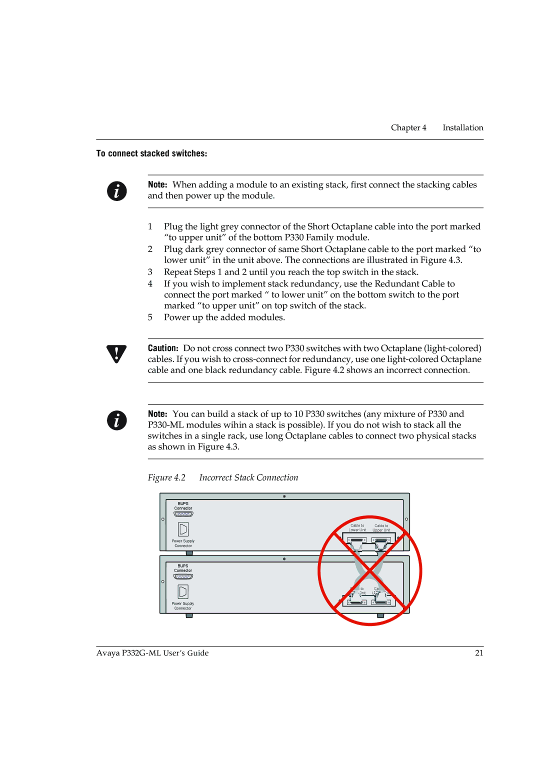
Caution: Do not cross connect two P330 switches with two Octaplane
Note: You can build a stack of up to 10 P330 switches (any mixture of P330 and
Figure 4.2 Incorrect Stack Connection
BUPS
Connector
Cable to | Cable to |
Lower Unit | Upper Unit |
Power Supply
Connector
BUPS
Connector
Cable to | Cable to |
Lower Unit | Upper Unit |
Power Supply
Connector
Avaya | 21 |