Chapter 4 | Installation |
|
|
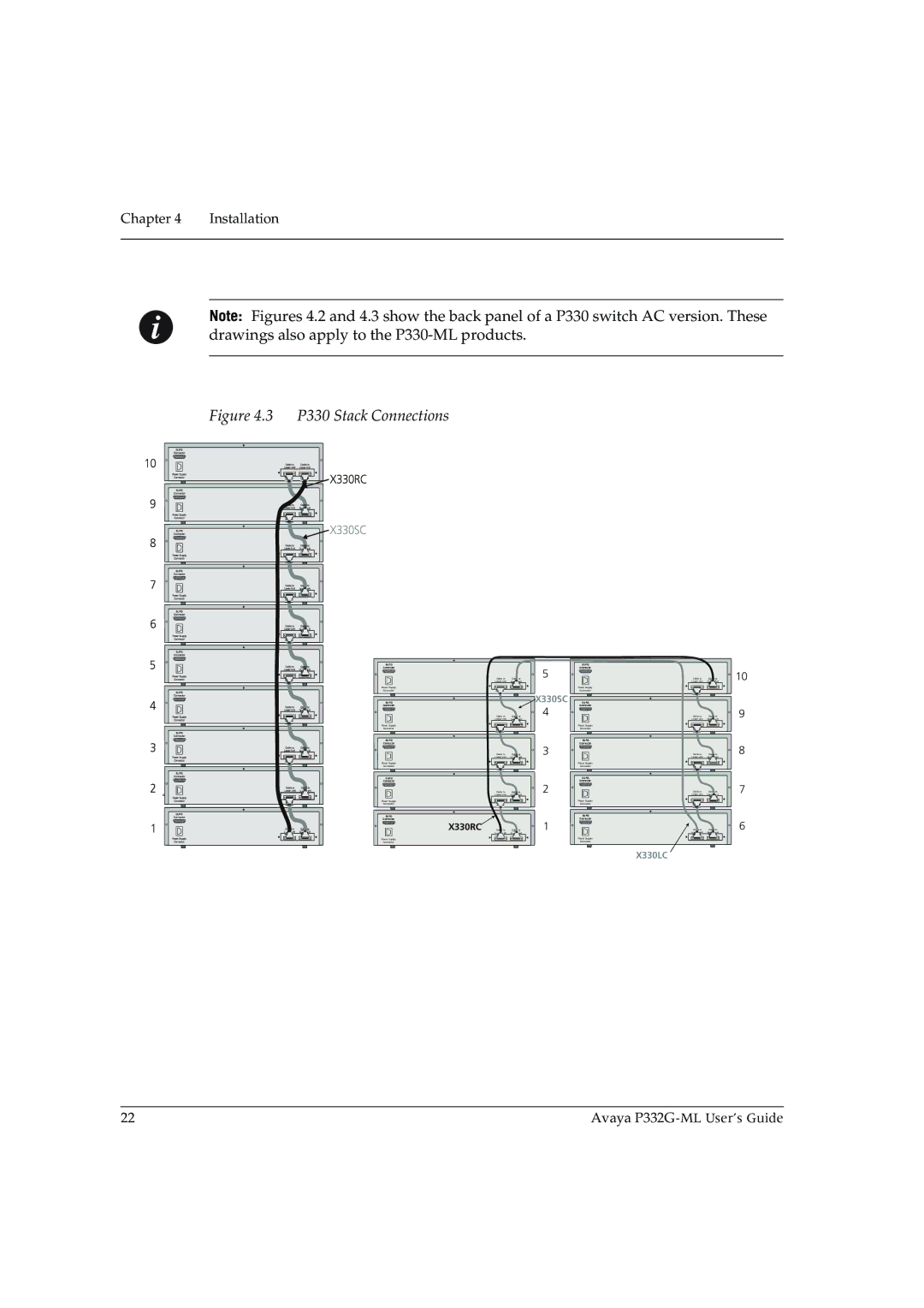
Note: Figures 4.2 and 4.3 show the back panel of a P330 switch AC version. These drawings also apply to the
Figure 4.3 P330 Stack Connections
BUPS
Connector
| Cable to | Cable to |
| Lower Unit | Upper Unit |
Power Supply |
|
|
Connector |
|
|
BUPS |
|
|
Connector |
|
|
| Cable to | Cable to |
| Lower Unit | Upper Unit |
Power Supply |
|
|
Connector |
|
|
BUPS |
|
|
Connector |
|
|
| Cable to | Cable to |
| Lower Unit | Upper Unit |
Power Supply |
|
|
Connector |
|
|
BUPS |
|
|
Connector |
|
|
| Cable to | Cable to |
| Lower Unit | Upper Unit |
Power Supply |
|
|
Connector |
|
|
BUPS |
|
|
Connector |
|
|
X330RC | Cable to | Cable to |
| Lower Unit | Upper Unit |
Power Supply
Connector
5
X330SC
4
3
2
1
BUPS
Connector
Cable to | Cable to |
Lower Unit | Upper Unit |
Power Supply |
|
Connector |
|
BUPS |
|
Connector |
|
Cable to | Cable to |
Lower Unit | Upper Unit |
Power Supply |
|
Connector |
|
BUPS |
|
Connector |
|
Cable to | Cable to |
Lower Unit | Upper Unit |
Power Supply |
|
Connector |
|
BUPS |
|
Connector |
|
Cable to | Cable to |
Lower Unit | Upper Unit |
Power Supply |
|
Connector |
|
BUPS |
|
Connector |
|
Cable to | Cable to |
Lower Unit | Upper Unit |
Power Supply
Connector
X330LC
![]() 10
10
9
8
7
6
22 | Avaya |