www.baldormotion.com
3.1.2 Mounting the DSM
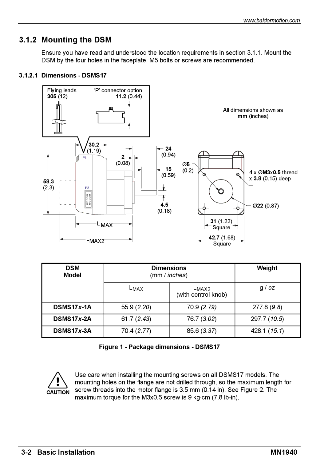
Ensure you have read and understood the location requirements in section 3.1.1. Mount the DSM by the four holes in the faceplate. M5 bolts or screws are recommended.
3.1.2.1 Dimensions - DSMS17
Flying leads | ‘P’ connector option |
305 (12) | 11.2 (0.44) |
| 30.2 | 24 |
|
| (1.19) |
| |
P1 | 2 | (0.94) |
|
| (0.08) | 15 | Ø5 |
|
| (0.2) | |
|
| (0.59) |
|
58.3
(2.3)P2
4.5
(0.18)
L MAX
LMAX2
All dimensions shown as
mm(inches)
4 x ØM3x0.5 thread x 3.8 (0.15) deep
Ø22 (0.87)
31(1.22)
Square
42.7(1.68)
Square
DSM |
| Dimensions | Weight | |
Model | (mm / inches) |
| ||
|
|
|
|
|
| LMAX |
| LMAX2 | g / oz |
|
|
| (with control knob) |
|
|
|
|
|
|
55.9 (2.20) |
| 70.9 (2.79) | 277.8 (9.8) | |
|
|
|
|
|
61.7 (2.43) |
| 76.7 (3.02) | 297.7 (10.5) | |
|
|
|
|
|
70.4 (2.77) |
| 85.6 (3.37) | 428.1 (15.1) | |
|
|
|
|
|
| Figure 1 - Package dimensions - DSMS17 |
| Use care when installing the mounting screws on all DSMS17 models. The |
| mounting holes on the flange are not drilled through, so the maximum length for |
CAUTION | screw threads into the motor flange is 3.5 mm (0.14 in). See Figure 2. The |
| maximum torque for the M3x0.5 screw is 9 kg·cm (7.8 |
| MN1940 |