www.baldormotion.com
4.4 SPI interface
DSM setup parameters are changed via an SPI (Serial Peripheral Interface) port. This port uses a
4.4.1 SPI connector
1 ![]()
![]()
3 ![]()
![]()
5 ![]()
![]()
7 ![]()
![]()
9 ![]()
![]()
| Location | ||
2 |
| Additional flying leads (DSMS34...) | |
| Typical mating connector: AMPMODU MT (Amp | ||
4 |
|
|
|
Pin | Name | Description | |
6 |
|
|
|
1 | (NC) |
| |
8 |
|
|
|
2 | (NC) |
| |
|
| ||
10 |
|
|
|
3 | (NC) |
| |
|
| ||
|
|
|
|
| 4 | CS | Chip select |
|
|
|
|
| 5 | GND | Communication ground |
|
|
|
|
| 6 | +5V out | +5 VDC output |
|
|
|
|
| 7 | MOSI | Master Out / Slave In |
|
|
|
|
| 8 | CLK | Clock |
|
|
|
|
| 9 | (NC) |
|
|
|
|
|
| 10 | MISO | Master In / Slave Out |
|
|
|
|
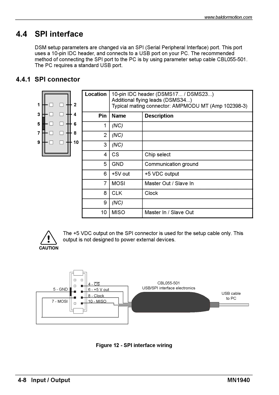
The +5 VDC output on the SPI connector is used for the setup cable only. This output is not designed to power external devices.
CAUTION
5 - GND ![]()
7 - MOSI
4 - CS
6 - +5 V out
8 - Clock
10 - MISO
USB/SPI interface electronics
USB cable
to PC
Figure 12 - SPI interface wiring
MN1940 |