www.baldormotion.com
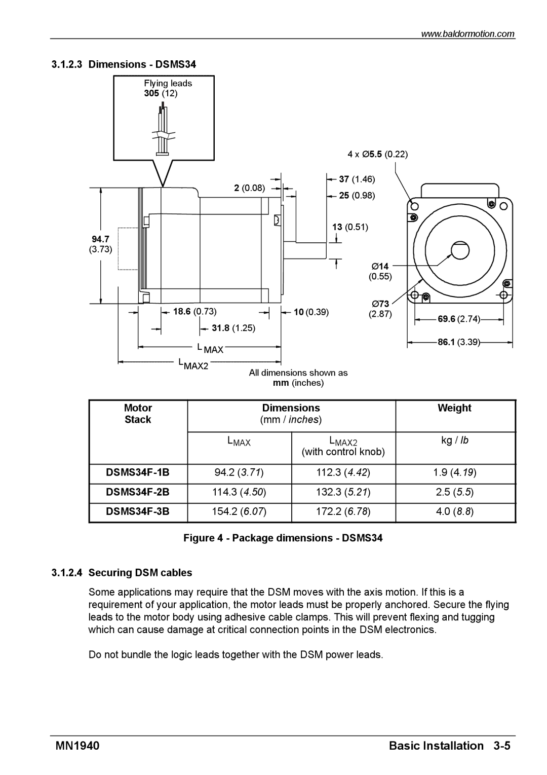
3.1.2.3 Dimensions - DSMS34
Flying leads
305(12)
4 x Ø5.5 (0.22)
![]() 37 (1.46) 2 (0.08)
37 (1.46) 2 (0.08) ![]()
![]()
![]() 25 (0.98)
25 (0.98)
13 (0.51)
94.7
(3.73)
|
| Ø14 |
|
|
| (0.55) |
|
18.6 (0.73) | 10 (0.39) | Ø73 |
|
(2.87) | 69.6 (2.74) | ||
31.8 (1.25) |
| ||
|
| ||
L MAX |
|
| 86.1 (3.39) |
|
|
| |
LMAX2 | All dimensions shown as |
|
|
| mm (inches) |
|
|
Motor |
| Dimensions | |
Stack |
| (mm / inches) | |
|
|
|
|
|
| LMAX | LMAX2 |
|
|
| (with control knob) |
|
|
|
|
| 94.2 (3.71) | 112.3 (4.42) | |
|
|
|
|
| 114.3 (4.50) | 132.3 (5.21) | |
|
|
|
|
|
| 154.2 (6.07) | 172.2 (6.78) |
|
|
|
|
| Figure 4 - Package dimensions - DSMS34 | ||
Weight
kg / lb
1.9(4.19)
2.5(5.5)
4.0(8.8)
3.1.2.4Securing DSM cables
Some applications may require that the DSM moves with the axis motion. If this is a requirement of your application, the motor leads must be properly anchored. Secure the flying leads to the motor body using adhesive cable clamps. This will prevent flexing and tugging which can cause damage at critical connection points in the DSM electronics.
Do not bundle the logic leads together with the DSM power leads.
MN1940 | Basic Installation |