www.baldormotion.com
4.5 Connection summary - minimum system wiring
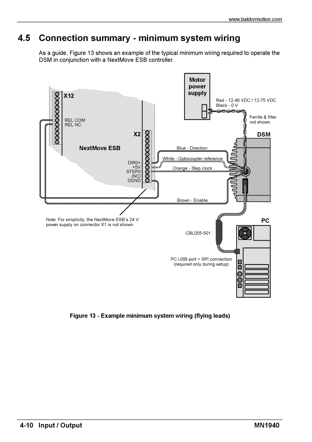
As a guide, Figure 13 shows an example of the typical minimum wiring required to operate the DSM in conjunction with a NextMove ESB controller.
| Motor | |
| power | |
X12 | supply | |
Red - | ||
| ||
| Black - 0 V | |
REL COM | Ferrite & filter | |
not shown. | ||
REL NC | ||
| ||
X2 | DSM | |
NextMove ESB | Blue - Direction | |
DIR0+ | White - Optocoupler reference | |
| ||
+5V | Orange - Step clock | |
STEP0 |
| |
(NC) |
| |
DGND |
| |
| Brown - Enable |
Note: For simplicity, the NextMove ESB’s 24 V power supply on connector X1 is not shown.
PC
PC USB port > SPI connection
(required only during setup)
Figure 13 - Example minimum system wiring (flying leads)
MN1940 |