www.baldormotion.com
4.3.3 Sinking / sourcing input configuration
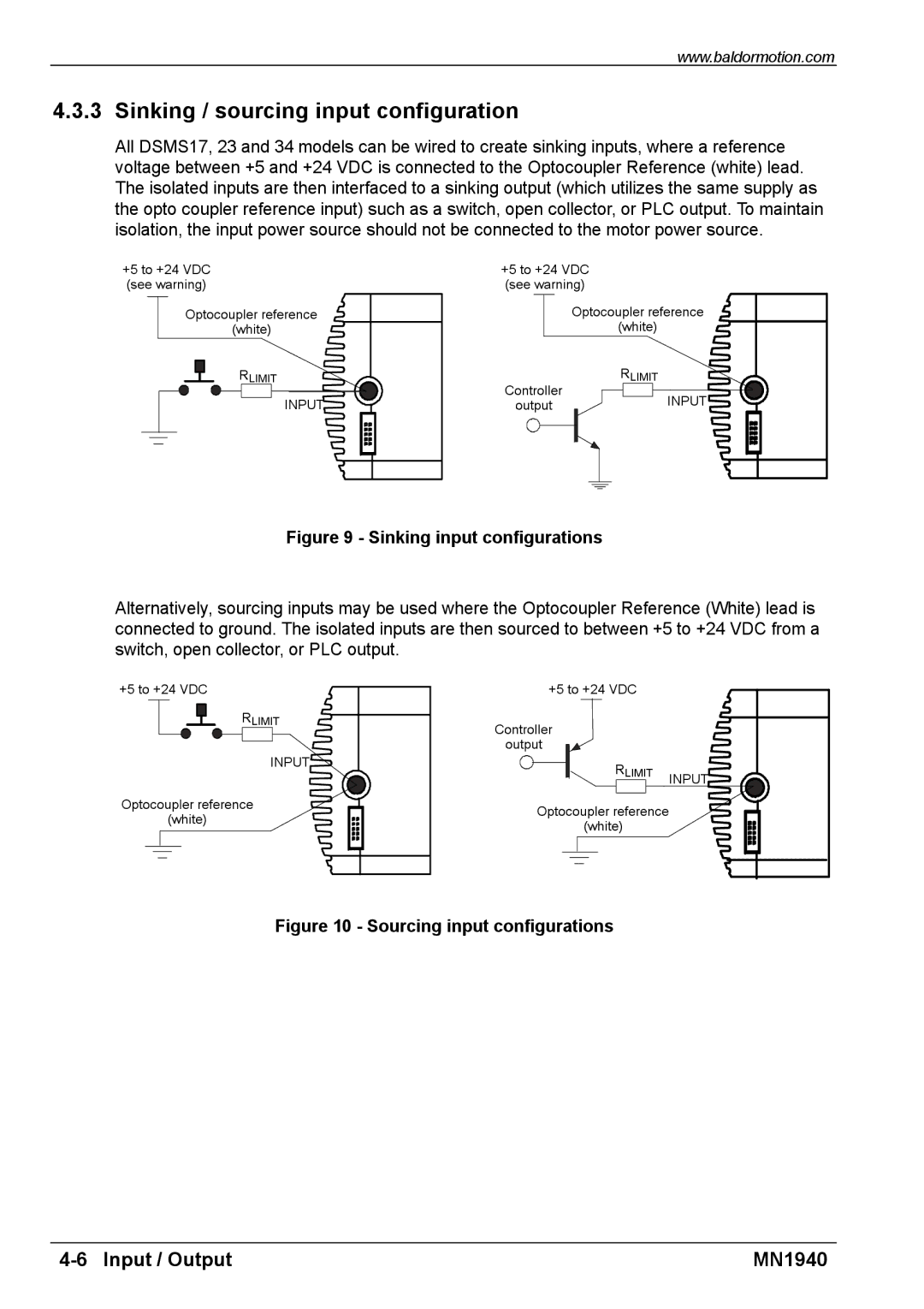
All DSMS17, 23 and 34 models can be wired to create sinking inputs, where a reference voltage between +5 and +24 VDC is connected to the Optocoupler Reference (white) lead. The isolated inputs are then interfaced to a sinking output (which utilizes the same supply as the opto coupler reference input) such as a switch, open collector, or PLC output. To maintain isolation, the input power source should not be connected to the motor power source.
+5 to +24 VDC | +5 to +24 VDC |
(see warning) | (see warning) |
Optocoupler reference | Optocoupler reference |
(white) | (white) |
RLIMIT | RLIMIT |
INPUT | Controller | INPUT |
output |
Figure 9 - Sinking input configurations
Alternatively, sourcing inputs may be used where the Optocoupler Reference (White) lead is connected to ground. The isolated inputs are then sourced to between +5 to +24 VDC from a switch, open collector, or PLC output.
+5 to +24 VDC | +5 to +24 VDC |
|
RLIMIT | Controller |
|
| output |
|
INPUT | RLIMIT | INPUT |
| ||
|
| |
Optocoupler reference | Optocoupler reference |
|
(white) |
| |
(white) |
| |
|
|
Figure 10 - Sourcing input configurations
MN1940 |