MIC Series 500 CameraMounting en 21
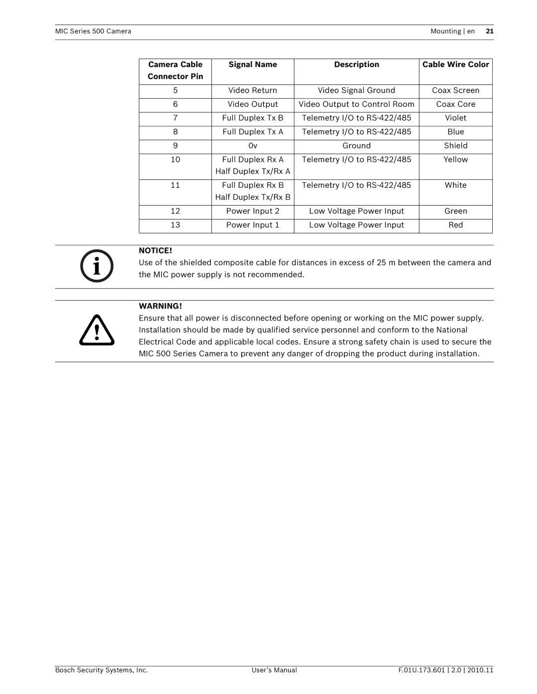
Camera Cable | Signal Name | Description | Cable Wire Color |
Connector Pin |
|
|
|
|
|
|
|
5 | Video Return | Video Signal Ground | Coax Screen |
|
|
|
|
6 | Video Output | Video Output to Control Room | Coax Core |
|
|
|
|
7 | Full Duplex Tx B | Telemetry I/O to | Violet |
|
|
|
|
8 | Full Duplex Tx A | Telemetry I/O to | Blue |
|
|
|
|
9 | 0v | Ground | Shield |
|
|
|
|
10 | Full Duplex Rx A | Telemetry I/O to | Yellow |
| Half Duplex Tx/Rx A |
|
|
|
|
|
|
11 | Full Duplex Rx B | Telemetry I/O to | White |
| Half Duplex Tx/Rx B |
|
|
|
|
|
|
12 | Power Input 2 | Low Voltage Power Input | Green |
|
|
|
|
13 | Power Input 1 | Low Voltage Power Input | Red |
|
|
|
|
NOTICE!
Use of the shielded composite cable for distances in excess of 25 m between the camera and the MIC power supply is not recommended.
WARNING!
Ensure that all power is disconnected before opening or working on the MIC power supply. Installation should be made by qualified service personnel and conform to the National Electrical Code and applicable local codes. Ensure a strong safety chain is used to secure the MIC 500 Series Camera to prevent any danger of dropping the product during installation.
Bosch Security Systems, Inc. | User’s Manual | F.01U.173.601 2.0 2010.11 |