MIC Series 500 Camera | Mounting en 19 |
|
|
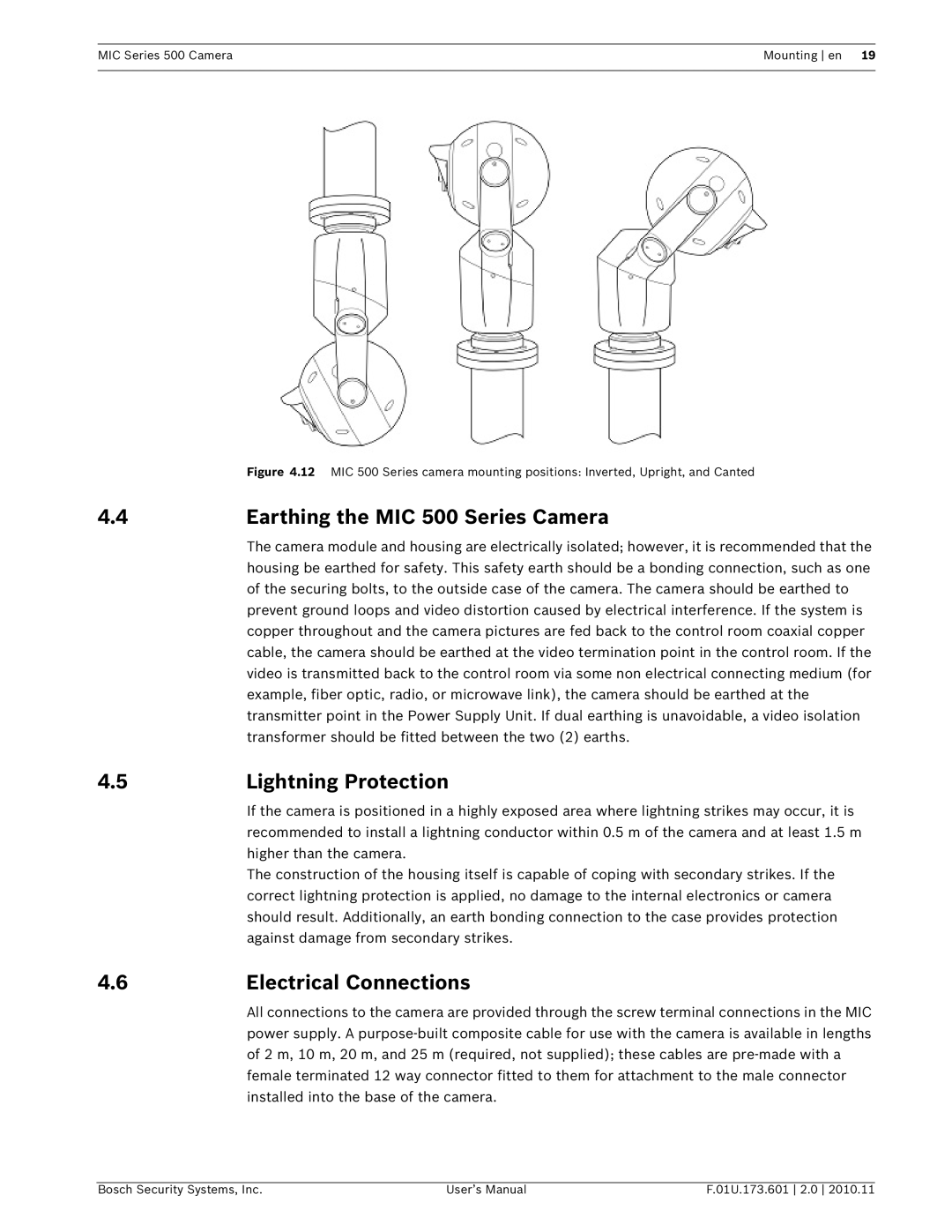
| Figure 4.12 MIC 500 Series camera mounting positions: Inverted, Upright, and Canted |
4.4 | Earthing the MIC 500 Series Camera |
| The camera module and housing are electrically isolated; however, it is recommended that the |
| housing be earthed for safety. This safety earth should be a bonding connection, such as one |
| of the securing bolts, to the outside case of the camera. The camera should be earthed to |
| prevent ground loops and video distortion caused by electrical interference. If the system is |
| copper throughout and the camera pictures are fed back to the control room coaxial copper |
| cable, the camera should be earthed at the video termination point in the control room. If the |
| video is transmitted back to the control room via some non electrical connecting medium (for |
| example, fiber optic, radio, or microwave link), the camera should be earthed at the |
| transmitter point in the Power Supply Unit. If dual earthing is unavoidable, a video isolation |
| transformer should be fitted between the two (2) earths. |
4.5 | Lightning Protection |
| If the camera is positioned in a highly exposed area where lightning strikes may occur, it is |
| recommended to install a lightning conductor within 0.5 m of the camera and at least 1.5 m |
| higher than the camera. |
| The construction of the housing itself is capable of coping with secondary strikes. If the |
| correct lightning protection is applied, no damage to the internal electronics or camera |
| should result. Additionally, an earth bonding connection to the case provides protection |
| against damage from secondary strikes. |
4.6 | Electrical Connections |
| All connections to the camera are provided through the screw terminal connections in the MIC |
power supply. A
Bosch Security Systems, Inc. | User’s Manual | F.01U.173.601 2.0 2010.11 |
