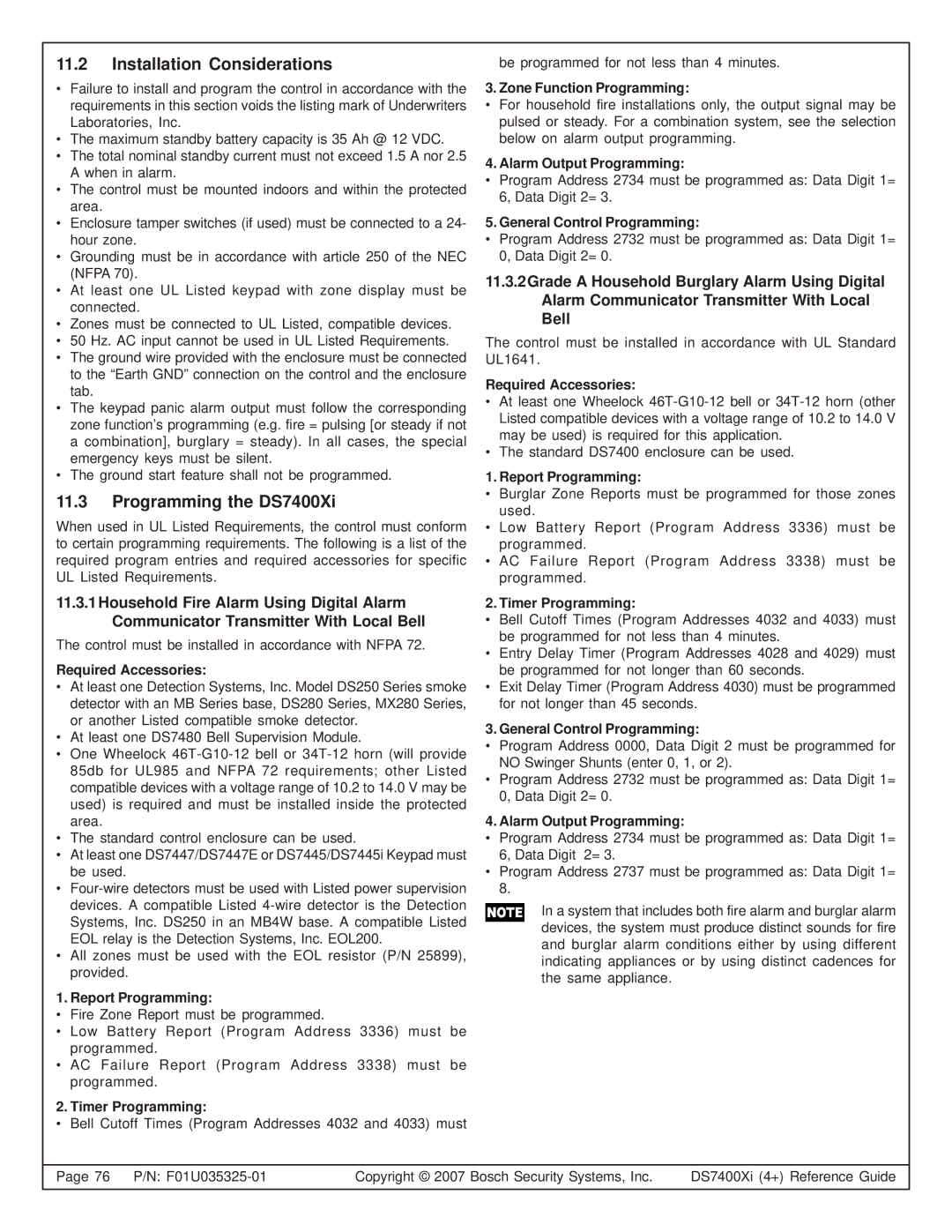
DS7445I, DS7447, DS7400XI, DS7447E specifications
Bosch Appliances offers a range of state-of-the-art home solutions, with models like the DS7447, DS7400XI, DS7445I, and DS7447E showcasing advanced technology and innovative design. Each of these models reflects Bosch's commitment to quality, efficiency, and user convenience.The Bosch DS7447 is designed for the modern kitchen. This model features a fully integrated design, allowing it to blend seamlessly into any cabinetry. With a spacious capacity, it accommodates various cooking needs, ensuring every home chef has ample room. Its intuitive control panel simplifies operation, allowing users to select temperature settings with ease. The energy-efficient technology contributes to lower utility bills while still delivering outstanding performance.
Moving on to the Bosch DS7400XI, this model stands out due to its sleek stainless steel finish, which not only enhances its aesthetic appeal but also offers durability. It is equipped with advanced cooling technology that ensures even temperature distribution, extending the lifespan of stored food. This model also incorporates a sophisticated air filtration system, eliminating unwanted odors and maintaining a fresh environment within the appliance. The adjustable shelving adds flexibility to storage options, accommodating items of varying sizes.
The Bosch DS7445I combines style and functionality. This particular model is highlighted by its quiet operation, making it a great choice for open-concept living spaces. With a focus on user-friendliness, it features a digital display and smart sensors that monitor performance and inform users when maintenance is required. Furthermore, this model is known for its eco-friendly operation, utilizing minimal energy without compromising on effectiveness, making it suitable for environmentally conscious households.
Finally, the Bosch DS7447E brings innovation to the forefront with its smart connectivity features. Users can control and monitor the appliance remotely via a smartphone app, allowing for a seamless cooking experience even when away from home. The model also boasts quick-cooling technology, ensuring that items are chilled faster without sacrificing quality. The design emphasis placed on user accessibility strengthens its appeal for diverse households.
In conclusion, Bosch Appliances' DS7447, DS7400XI, DS7445I, and DS7447E each offer unique benefits tailored to meet various needs. With exceptional quality, advanced technologies, and user-centered designs, Bosch continues to position itself as a leader in the home appliance market.

