Chapter 4: Examples
4.2.2Frame Handling
The following describes how, when User A attempts to log on to the File Server on Bridge 4, the frames from User A are classified on Switch 4 and traverse the network. In this example, the MAC address of User A is “Y” and the MAC address for the File Server is “Z”. The following description includes illustrations to help understand how the frames flow through the network.
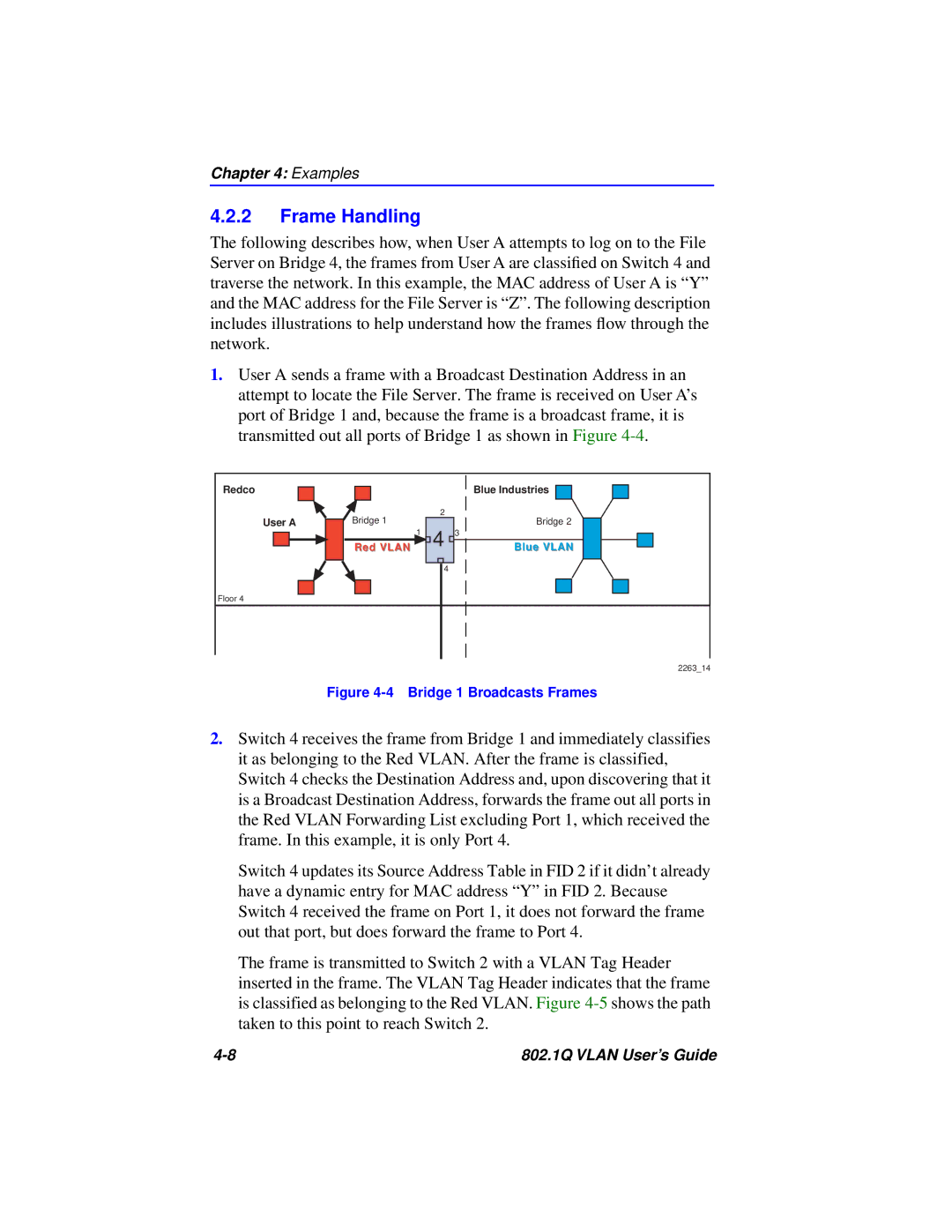
1.User A sends a frame with a Broadcast Destination Address in an attempt to locate the File Server. The frame is received on User A’s port of Bridge 1 and, because the frame is a broadcast frame, it is transmitted out all ports of Bridge 1 as shown in Figure
Redco |
|
|
| Blue Industries | |
User A | Bridge 1 |
| 2 | Bridge 2 | |
1 | 4 3 | ||||
| Red VLAN | Blue VLAN | |||
|
|
| 4 |
| |
Floor 4 |
|
|
|
|
2263_14
Figure 4-4 Bridge 1 Broadcasts Frames
2.Switch 4 receives the frame from Bridge 1 and immediately classifies it as belonging to the Red VLAN. After the frame is classified, Switch 4 checks the Destination Address and, upon discovering that it is a Broadcast Destination Address, forwards the frame out all ports in the Red VLAN Forwarding List excluding Port 1, which received the frame. In this example, it is only Port 4.
Switch 4 updates its Source Address Table in FID 2 if it didn’t already have a dynamic entry for MAC address “Y” in FID 2. Because Switch 4 received the frame on Port 1, it does not forward the frame out that port, but does forward the frame to Port 4.
The frame is transmitted to Switch 2 with a VLAN Tag Header inserted in the frame. The VLAN Tag Header indicates that the frame is classified as belonging to the Red VLAN. Figure
802.1Q VLAN User’s Guide |