Chapter 4: Examples |
|
|
|
|
|
|
User B |
|
|
|
|
|
|
Bridge 1 |
| 2 | Bridge 2 |
|
|
|
|
|
|
|
| ||
Red VLAN | 1 | 4 3 | Blue VLAN |
|
|
|
|
| 4 |
|
|
|
|
Floor 4 |
|
|
|
|
|
|
|
|
| Publications |
|
|
|
|
| 2 |
| 2 | 3 | Grey VLAN |
|
|
|
|
| 4 | Printer |
| 1 | 3 3 | Yellow VLAN1 | 5 65 |
| |
|
| 4 |
| 8 | 7 |
|
Floor 3 |
|
|
|
|
|
|
|
| 2 | Bridge 4 |
|
| File Server |
Bridge 3 |
|
|
|
| ||
| 2 3 |
|
|
|
| |
Blue VLAN | 1 | Red VLAN |
|
|
| |
|
| 4 |
|
|
|
|
Floor 2 |
|
|
|
|
|
|
Green, Inc. |
|
|
|
|
|
|
|
| 2 | Mail Server |
|
|
|
|
|
|
|
|
| |
Green VLAN1 | 1 3 |
|
|
|
| |
Floor 1 |
|
|
|
|
|
|
User
802.1D Legacy Bridge
802.1Q
Server
2599_18
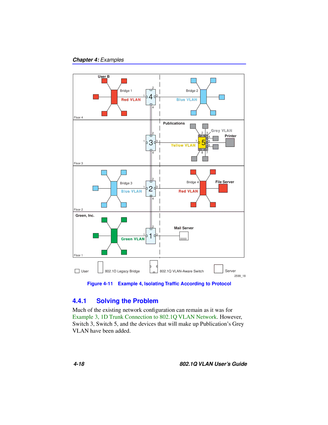
Figure 4-11 Example 4, Isolating Traffic According to Protocol
4.4.1Solving the Problem
Much of the existing network configuration can remain as it was for Example 3, 1D Trunk Connection to 802.1Q VLAN Network. However, Switch 3, Switch 5, and the devices that will make up Publication’s Grey VLAN have been added.
802.1Q VLAN User’s Guide |
