Example 2, VLANs Across Multiple Switches
Redco
Blue Industries
| Bridge 1 |
| 2 | Bridge 2 |
User A |
| 4 3 | ||
| Red VLAN | 1 | Blue VLAN | |
|
|
| 4 |
|
Floor 4
Floor 3 |
|
|
|
|
|
Blue Industries |
|
|
| Redco |
|
File Server |
|
| 2 | Bridge 4 | File Server |
Bridge 3 |
|
| |||
|
| 2 3 |
|
| |
| Blue VLAN | 1 | Red VLAN |
| |
Floor 2 |
|
|
|
|
|
Floor 1
User
802.1D Legacy Bridge
802.1Q VLAN Aware Switch
File Server
22632_13
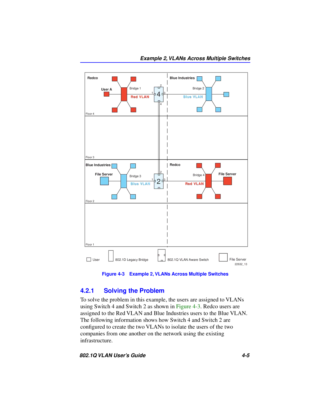
Figure 4-3 Example 2, VLANs Across Multiple Switches
4.2.1Solving the Problem
To solve the problem in this example, the users are assigned to VLANs using Switch 4 and Switch 2 as shown in Figure
802.1Q VLAN User’s Guide |