Example 3, 1D Trunk Connection to 802.1Q VLAN Network
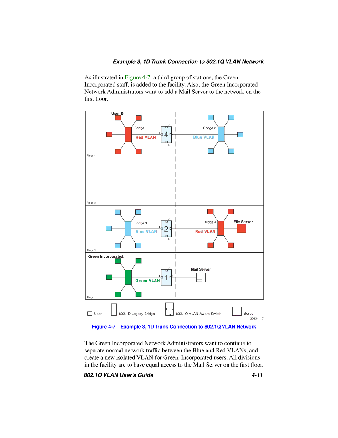
As illustrated in Figure
User B
Bridge 1 |
| 2 | Bridge 2 |
|
| ||
Red VLAN | 1 | 4 3 | Blue VLAN |
|
| 4 |
|
Floor 4
Floor 3
|
| 2 | Bridge 4 | File Server |
Bridge 3 |
|
| ||
| 2 3 |
|
| |
Blue VLAN | 1 | Red VLAN |
| |
|
| 4 |
|
|
Floor 2
Green Incorporated.
| 2 | Mail Server |
|
| |
Green VLAN1 | 1 3 |
|
Floor 1
User
802.1D Legacy Bridge
802.1Q
Server
22631_17
Figure 4-7 Example 3, 1D Trunk Connection to 802.1Q VLAN Network
The Green Incorporated Network Administrators want to continue to separate normal network traffic between the Blue and Red VLANs, and create a new isolated VLAN for Green, Incorporated users. All divisions in the facility are to have equal access to the Mail Server on the first floor.
802.1Q VLAN User’s Guide |