Do not pressure test gas supply while connected to unit. Always disconnect union before servicing.
IMPORTANT: Natural gas pressure at unit gas connection must not be less than 5.5 in. wg or greater than 13.0 in. wg.
Size
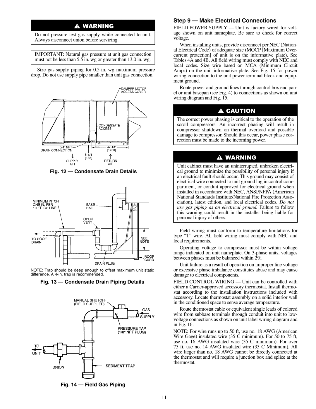
Fig. 12 — Condensate Drain Details
NOTE: Trap should be deep enough to offset maximum unit static difference. A
Fig. 13 — Condensate Drain Piping Details
Fig. 14 — Field Gas Piping
Step 9 — Make Electrical Connections
FIELD POWER SUPPLY — Unit is factory wired for volt- age shown on unit nameplate. Be sure to check for correct voltage.
When installing units, provide disconnect per NEC (Nation- al Electrical Code) of adequate size (MOCP [Maximum Over- current protection] of unit is on the informative plate). See Tables 4A and 4B. All field wiring must comply with NEC and local codes. Size wire based on MCA (Minimum Circuit Amps) on the unit informative plate. See Fig. 15 for power wiring connection to the unit power terminal block and equip- ment ground.
Route power and ground lines through control box end pan- el or unit basepan (see Fig. 4) to connections as shown on unit wiring diagram and Fig. 15.
The correct power phasing is critical to the operation of the scroll compressors. An incorrect phasing will result in compressor shutdown on thermal overload and possible damage to compressor. Should this occur, power phase cor- rection must be made to the incoming power.
Unit cabinet must have an uninterrupted, unbroken electri- cal ground to minimize the possibility of personal injury if an electrical fault should occur. This ground may consist of electrical wire connected to unit ground lug in control com- partment, or conduit approved for electrical ground when installed in accordance with NEC, ANSI/NFPA (American National Standards Institute/National Fire Protection Asso- ciation), latest edition, and local electrical codes. Do not use gas piping as an electrical ground. Failure to follow this warning could result in the installer being liable for personal injury of others.
Field wiring must conform to temperature limitations for type “T” wire. All field wiring must comply with NEC and local requirements.
Operating voltage to compressor must be within voltage range indicated on unit nameplate. On
Unit failure as a result of operation on improper line voltage or excessive phase imbalance constitutes abuse and may cause damage to electrical components.
FIELD CONTROL WIRING — Unit can be controlled with either a
Route thermostat cable or equivalent single leads of colored wire from subbase terminals through conduit into unit to low- voltage connections as shown on unit label wiring diagram and in Fig. 16.
NOTE: For wire runs up to 50 ft, use no. 18 AWG (American Wire Gage) insulated wire (35 C minimum). For 50 to 75 ft, use no. 16 AWG insulated wire (35 C minimum). For over 75 ft, use no. 14 AWG insulated wire (35 C Minimum). All wire larger than no. 18 AWG cannot be directly connected at the thermostat and will require a junction box and splice at the thermostat.
11