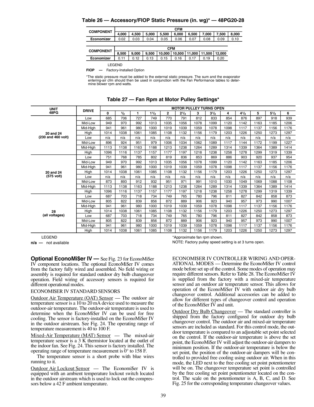
Table 26 — Accessory/FIOP Static Pressure (in. wg)* — 48PG20-28
COMPONENT |
|
|
|
| CFM |
|
|
|
| |
4,000 | 4,500 | 5,000 | 5,500 | 6,000 | 6,500 | 7,000 | 7,500 | 8,000 | ||
| ||||||||||
Economizer | 0.02 | 0.03 | 0.04 | 0.05 | 0.06 | 0.07 | 0.08 | 0.09 | 0.10 | |
|
|
|
|
|
|
|
|
|
| |
COMPONENT |
|
|
| CFM |
|
|
|
| ||
8,500 | 9,000 | 9,500 | 10,000 | 10,500 | 11,000 | 11,500 | 12,000 |
| ||
|
| |||||||||
Economizer | 0.11 | 0.12 | 0.13 | 0.15 | 0.16 | 0.17 | 0.19 | 0.20 |
| |
LEGEND
FIOP —
*The static pressure must be added to the external static pressure. The sum and the evaporator
Table 27 — Fan Rpm at Motor Pulley Settings*
UNIT | DRIVE |
|
|
|
| MOTOR PULLEY TURNS OPEN |
|
|
|
| ||||||
48PG | 0 | 1/2 | 1 | 11/2 | 2 |
| 21/2 | 3 | 31/2 |
| 4 | 41/2 | 5 | 51/2 | 6 | |
|
|
| ||||||||||||||
| Low | 685 | 706 | 727 | 749 | 770 |
| 791 | 812 | 833 |
| 854 | 876 | 897 | 918 | 939 |
| 949 | 970 | 992 | 1013 | 1035 |
| 1056 | 1078 | 1099 |
| 1120 | 1142 | 1163 | 1185 | 1206 | |
| 941 | 961 | 980 | 1000 | 1019 |
| 1039 | 1059 | 1078 |
| 1098 | 1117 | 1137 | 1156 | 1176 | |
20 and 24 | High | 1014 | 1038 | 1061 | 1085 | 1108 |
| 1132 | 1156 | 1179 |
| 1203 | 1226 | 1250 | 1273 | 1297 |
(230 and 460 volt) | Low | n/a | n/a | n/a | n/a | n/a |
| n/a | n/a | n/a |
| n/a | n/a | n/a | n/a | n/a |
| 896 | 924 | 951 | 979 | 1006 |
| 1034 | 1062 | 1089 |
| 1117 | 1144 | 1172 | 1199 | 1227 | |
| 1113 | 1138 | 1163 | 1188 | 1213 |
| 1238 | 1264 | 1289 |
| 1314 | 1339 | 1364 | 1389 | 1414 | |
| High | 1096 | 1116 | 1137 | 1157 | 1177 |
| 1197 | 1218 | 1238 |
| 1258 | 1278 | 1299 | 1319 | 1339 |
| Low | 751 | 768 | 785 | 802 | 819 |
| 836 | 853 | 869 |
| 886 | 903 | 920 | 937 | 954 |
| 949 | 970 | 992 | 1013 | 1035 |
| 1056 | 1078 | 1099 |
| 1120 | 1142 | 1163 | 1185 | 1206 | |
| 941 | 961 | 980 | 1000 | 1019 |
| 1039 | 1059 | 1078 |
| 1098 | 1117 | 1137 | 1156 | 1176 | |
20 and 24 | High | 1014 | 1038 | 1061 | 1085 | 1108 |
| 1132 | 1156 | 1179 |
| 1203 | 1226 | 1250 | 1273 | 1297 |
(575 volt) | Low | n/a | n/a | n/a | n/a | n/a |
| n/a | n/a | n/a |
| n/a | n/a | n/a | n/a | n/a |
| 873 | 893 | 912 | 932 | 951 |
| 971 | 991 | 1010 |
| 1030 | 1049 | 1069 | 1088 | 1108 | |
| 1113 | 1138 | 1163 | 1188 | 1213 |
| 1238 | 1264 | 1289 |
| 1314 | 1339 | 1364 | 1389 | 1414 | |
| High | 1096 | 1116 | 1137 | 1157 | 1177 |
| 1197 | 1218 | 1238 |
| 1258 | 1278 | 1299 | 1319 | 1339 |
| Low | 687 | 703 | 718 | 734 | 749 |
| 765 | 780 | 796 |
| 811 | 827 | 842 | 858 | 873 |
| 805 | 822 | 839 | 856 | 872 |
| 889 | 906 | 923 |
| 940 | 957 | 973 | 990 | 1007 | |
| 941 | 961 | 980 | 1000 | 1019 |
| 1039 | 1059 | 1078 |
| 1098 | 1117 | 1137 | 1156 | 1176 | |
28 | High | 1014 | 1038 | 1061 | 1085 | 1108 |
| 1132 | 1156 | 1179 |
| 1203 | 1226 | 1250 | 1273 | 1297 |
(all voltages) | Low | 687 | 703 | 718 | 734 | 749 |
| 765 | 780 | 796 |
| 811 | 827 | 842 | 858 | 873 |
| 805 | 822 | 839 | 856 | 872 |
| 889 | 906 | 923 |
| 940 | 957 | 973 | 990 | 1007 | |
| 941 | 961 | 980 | 1000 | 1019 |
| 1039 | 1059 | 1078 |
| 1098 | 1117 | 1137 | 1156 | 1176 | |
| High | 1014 | 1038 | 1061 | 1085 | 1108 |
| 1132 | 1156 | 1179 |
| 1203 | 1226 | 1250 | 1273 | 1297 |
LEGEND |
|
|
|
|
|
| *Approximate fan rpm shown. |
|
|
|
|
| ||||
n/a — not available |
|
|
|
|
|
| NOTE: Factory pulley speed setting is at 3 turns open. |
|
| |||||||
Optional EconoMi$er IV — See Fig. 23 for EconoMi$er IV component locations. The optional EconoMi$er IV comes from the factory fully wired and assembled. No field wiring or assembly is required for standard outdoor dry bulb changeover operation. Field wiring of accessory sensors is required for different operational modes.
ECONOMI$ER IV STANDARD SENSORS
Outdoor Air Temperature (OAT) Sensor — The outdoor air temperature sensor is a 10 to 20 mA device used to measure the
The temperature sensor is a short probe with blue wires running to it.
Outdoor Air Lockout Sensor — The Economi$er IV is equipped with an ambient temperature lockout switch located in the outdoor airstream which is used to lock out the compres- sors below a 42 F ambient temperature.
ECONOMI$ER IV CONTROLLER WIRING AND OPER- ATIONAL MODES — Determine the EconoMi$er IV control mode before set up of the control. Some modes of operation may require different sensors. Refer to Table 28. The EconoMi$er IV is supplied from the factory with a
Outdoor Dry Bulb Changeover — The standard controller is shipped from the factory configured for outdoor dry bulb changeover control. The outdoor air and
39