When ignition occurs the IGC board will continue to moni- tor the condition of the rollout and limit switches, the hall effect sensor, as well as the flame sensor. If the unit is controlled through a room thermostat set for fan auto., 45 seconds after ignition occurs, the
When additional heat is required, W2 closes and initiates power to the second stage of the main gas valve. When the thermostat is satisfied, W1 and W2 open and the gas valve closes, interrupting the flow of gas to the main burners. If the call for W1 lasted less than 1 minute, the heating cycle will not terminate until 1 minute after W1 became active. If the unit is controlled through a room thermostat set for fan auto., the
A LED indicator is provided on the IGC to monitor opera- tion. The IGC is located by removing the side panel and view- ing the IGC through the view port located in the control box access panel. During normal operation, the LED is continuous- ly on. For information on troubleshooting refer to page 57.
COOLING, UNITS WITH ECONOMI$ER IV — When free cooling is not available, the compressors will be controlled by the zone thermostat. When free cooling is available, the
If mechanical cooling is utilized with free cooling, the
If optional power exhaust is installed, as the
If
For EconoMi$er IV operation, there must be a thermostat call for the fan (G). This will move the damper to its minimum position.
When the EconoMi$er IV control is in the occupied mode and a call for cooling exists (Y1 on the thermostat), the control will first check for indoor fan operation. If the fan is not on, then cooling will not be activated. If the fan is on, then the control will open the EconoMi$er IV damper to the minimum position.
On the initial power to the EconoMi$er IV control, it will take the damper up to 21/2 minutes before it begins to position itself. Any change in damper position will take up to 30 sec- onds to initiate. Damper movement from full closed to full open (or vice versa) will take between 11/2 and 21/2 minutes.
If free cooling can be used as determined from the appropri- ate changeover command (switch, dry bulb, enthalpy curve, differential dry bulb, or differential enthalpy), then the control will modulate the dampers open to maintain the
If there is a further demand for cooling (cooling second stage — Y2 is energized), then the control will bring on compressor stage 1 to maintain the
HEATING, UNITS WITH ECONOMI$ER IV — When the room temperature calls for heat, the heating controls are energized as described in the Heating, Units Without Econo- mizer section. The IFM is energized and the EconoMi$er IV damper modulates to the minimum position. When the thermo- stat is satisfied and W1 and W2 are deenergized, the IFM continues to run, and the economizer damper modulates to the minimum position.
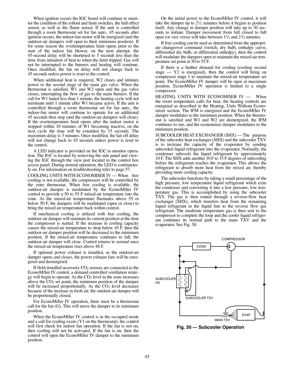
SUBCOOLER HEAT EXCHANGER (SHX) — The purpose of the subcooler heat exchanger (SHX) and the subcooler TXV is to increase the capacity of the evaporator by sending subcooled liquid refrigerant into the evaporator. Normally, the condenser subcools the liquid refrigerant by approximately 10 F. The SHX adds another 10 F to 15 F degrees of subcooling before the refrigerant reaches the evaporator. This allows the refrigerant to absorb more heat from the mixed air, thereby providing more cooling capacity.
The subcooler functions by taking a small percentage of the high pressure, low temperature liquid refrigerant which exits the condenser and converting it into a low pressure, low tem- perature gas. This is accomplished by using the subcooler TXV. The gas is then routed through a
COMPRESSOR
COND
SUBCOOLER
HX
SUBCOOLER TXV
EVAP
MAIN TXV
Fig. 30 — Subcooler Operation
45