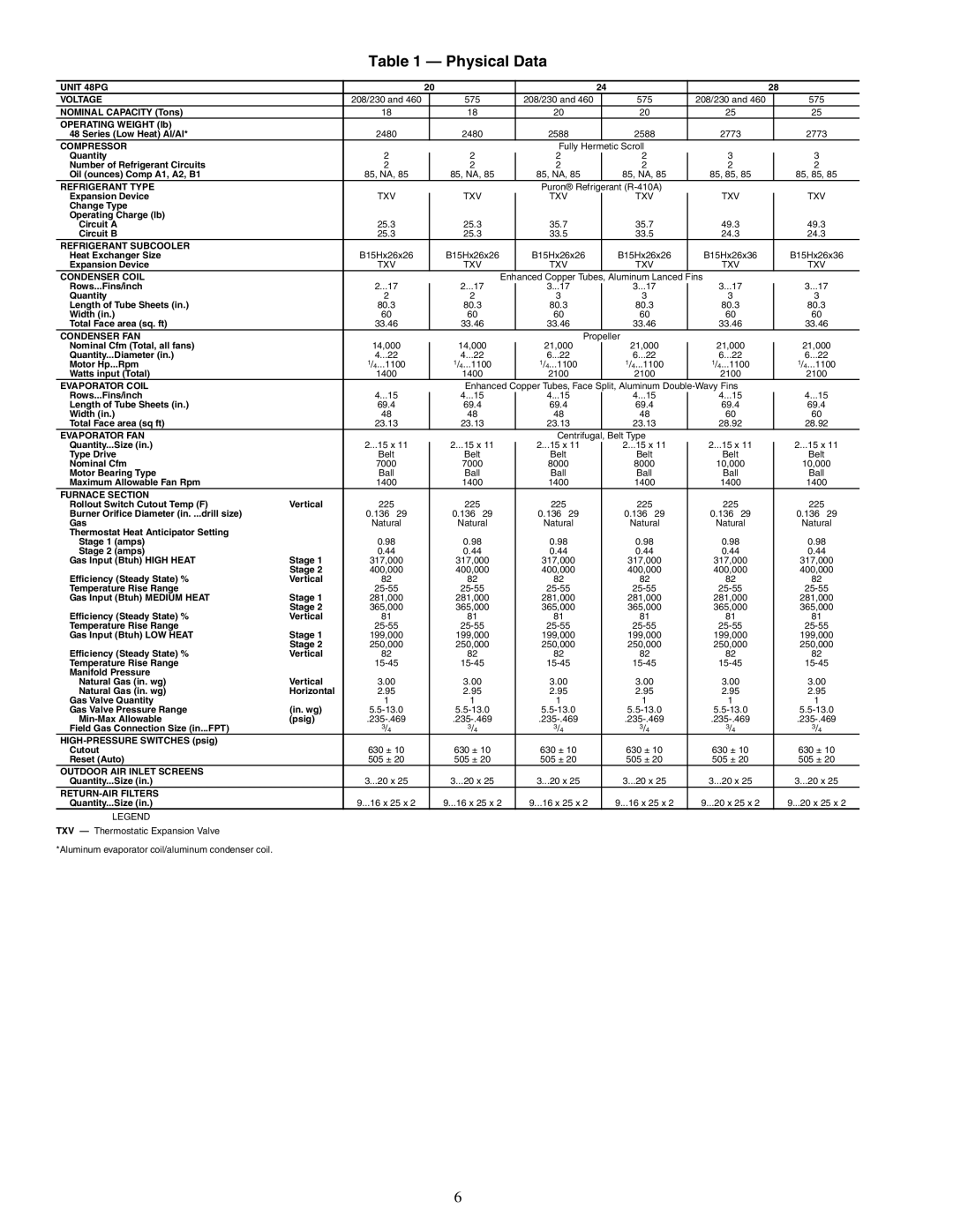
Table 1 — Physical Data
UNIT 48PG |
| 20 |
|
|
| 24 |
|
| 28 | ||||||
VOLTAGE |
| 208/230 and 460 |
|
| 575 |
| 208/230 and 460 |
|
| 575 |
| 208/230 and 460 |
|
| 575 |
NOMINAL CAPACITY (Tons) |
| 18 |
|
| 18 |
| 20 |
|
| 20 |
| 25 |
|
| 25 |
OPERATING WEIGHT (lb) |
|
|
|
|
|
|
|
|
|
|
|
|
|
|
|
48 Series (Low Heat) Al/Al* |
| 2480 |
|
| 2480 |
| 2588 |
|
| 2588 |
| 2773 |
|
| 2773 |
COMPRESSOR |
|
|
|
|
|
| Fully Hermetic Scroll |
|
|
|
|
| |||
Quantity |
| 2 |
|
| 2 |
| 2 |
|
| 2 |
| 3 |
|
| 3 |
|
|
|
|
|
|
| |||||||||
Number of Refrigerant Circuits |
| 2 |
|
| 2 |
| 2 |
|
| 2 |
| 2 |
|
| 2 |
Oil (ounces) Comp A1, A2, B1 |
| 85, NA, 85 |
|
| 85, NA, 85 |
| 85, NA, 85 |
|
| 85, NA, 85 |
| 85, 85, 85 |
|
| 85, 85, 85 |
REFRIGERANT TYPE |
|
|
|
|
|
| Puron® Refrigerant |
|
|
|
|
| |||
Expansion Device |
| TXV |
|
| TXV |
| TXV |
|
| TXV |
| TXV |
|
| TXV |
Change Type |
|
|
|
|
|
|
|
|
|
|
|
|
|
|
|
Operating Charge (lb) |
|
|
|
|
|
|
|
|
|
|
|
|
|
|
|
Circuit A |
| 25.3 |
|
| 25.3 |
| 35.7 |
|
| 35.7 |
| 49.3 |
|
| 49.3 |
Circuit B |
| 25.3 |
|
| 25.3 |
| 33.5 |
|
| 33.5 |
| 24.3 |
|
| 24.3 |
REFRIGERANT SUBCOOLER |
|
|
|
|
|
|
|
|
|
|
|
|
|
|
|
Heat Exchanger Size |
| B15Hx26x26 |
|
| B15Hx26x26 |
| B15Hx26x26 |
|
| B15Hx26x26 |
| B15Hx26x36 |
|
| B15Hx26x36 |
Expansion Device |
| TXV |
|
| TXV |
| TXV |
|
| TXV |
| TXV |
|
| TXV |
CONDENSER COIL |
|
|
|
| Enhanced Copper Tubes, Aluminum Lanced Fins |
|
|
| |||||||
Rows...Fins/inch |
| 2...17 |
|
| 2...17 |
| 3...17 |
|
| 3...17 |
| 3...17 |
|
| 3...17 |
|
|
|
|
|
|
| |||||||||
Quantity |
| 2 |
|
| 2 |
| 3 |
|
| 3 |
| 3 |
|
| 3 |
Length of Tube Sheets (in.) |
| 80.3 |
|
| 80.3 |
| 80.3 |
|
| 80.3 |
| 80.3 |
|
| 80.3 |
Width (in.) |
| 60 |
|
| 60 |
| 60 |
|
| 60 |
| 60 |
|
| 60 |
Total Face area (sq. ft) |
| 33.46 |
|
| 33.46 |
| 33.46 |
|
| 33.46 |
| 33.46 |
|
| 33.46 |
CONDENSER FAN |
|
|
|
|
|
| Propeller |
|
|
|
|
| |||
Nominal Cfm (Total, all fans) |
| 14,000 |
|
| 14,000 |
| 21,000 |
|
| 21,000 |
| 21,000 |
|
| 21,000 |
Quantity...Diameter (in.) |
| 4...22 |
|
| 4...22 |
| 6...22 |
|
| 6...22 |
| 6...22 |
|
| 6...22 |
Motor Hp...Rpm |
| 1/4...1100 |
|
| 1/4...1100 |
| 1/4...1100 |
|
| 1/4...1100 |
| 1/4...1100 |
|
| 1/4...1100 |
Watts input (Total) |
| 1400 |
|
| 1400 |
| 2100 |
|
| 2100 |
| 2100 |
|
| 2100 |
EVAPORATOR COIL |
|
|
|
| Enhanced Copper Tubes, Face Split, Aluminum |
|
|
| |||||||
Rows...Fins/inch |
| 4...15 |
|
| 4...15 |
| 4...15 |
|
| 4...15 |
| 4...15 |
|
| 4...15 |
|
|
|
|
|
|
| |||||||||
Length of Tube Sheets (in.) |
| 69.4 |
|
| 69.4 |
| 69.4 |
|
| 69.4 |
| 69.4 |
|
| 69.4 |
Width (in.) |
| 48 |
|
| 48 |
| 48 |
|
| 48 |
| 60 |
|
| 60 |
Total Face area (sq ft) |
| 23.13 |
|
| 23.13 |
| 23.13 |
|
| 23.13 |
| 28.92 |
|
| 28.92 |
EVAPORATOR FAN |
|
|
|
|
|
| Centrifugal, Belt Type |
|
|
|
|
| |||
Quantity...Size (in.) |
| 2...15 x 11 |
|
| 2...15 x 11 |
| 2...15 x 11 |
|
| 2...15 x 11 |
| 2...15 x 11 |
|
| 2...15 x 11 |
|
|
|
|
|
| ||||||||||
Type Drive |
| Belt |
|
| Belt |
| Belt |
|
| Belt |
| Belt |
|
| Belt |
Nominal Cfm |
| 7000 |
|
| 7000 |
| 8000 |
|
| 8000 |
| 10,000 |
|
| 10,000 |
Motor Bearing Type |
| Ball |
|
| Ball |
| Ball |
|
| Ball |
| Ball |
|
| Ball |
Maximum Allowable Fan Rpm |
| 1400 |
|
| 1400 |
| 1400 |
|
| 1400 |
| 1400 |
|
| 1400 |
FURNACE SECTION |
|
|
|
|
|
|
|
|
|
|
|
|
|
|
|
Rollout Switch Cutout Temp (F) | Vertical | 225 |
|
| 225 |
| 225 |
|
| 225 |
| 225 |
|
| 225 |
Burner Orifice Diameter (in. ...drill size) |
| 0.136...29 |
|
| 0.136...29 |
| 0.136...29 |
|
| 0.136...29 |
| 0.136...29 |
|
| 0.136...29 |
Gas |
| Natural |
|
| Natural |
| Natural |
|
| Natural |
| Natural |
|
| Natural |
Thermostat Heat Anticipator Setting |
|
|
|
|
|
|
|
|
|
|
|
|
|
|
|
Stage 1 (amps) |
| 0.98 |
|
| 0.98 |
| 0.98 |
|
| 0.98 |
| 0.98 |
|
| 0.98 |
Stage 2 (amps) |
| 0.44 |
|
| 0.44 |
| 0.44 |
|
| 0.44 |
| 0.44 |
|
| 0.44 |
Gas Input (Btuh) HIGH HEAT | Stage 1 | 317,000 |
|
| 317,000 |
| 317,000 |
|
| 317,000 |
| 317,000 |
|
| 317,000 |
| Stage 2 | 400,000 |
|
| 400,000 |
| 400,000 |
|
| 400,000 |
| 400,000 |
|
| 400,000 |
Efficiency (Steady State) % | Vertical | 82 |
|
| 82 |
| 82 |
|
| 82 |
| 82 |
|
| 82 |
Temperature Rise Range |
|
|
|
|
|
|
|
|
| ||||||
Gas Input (Btuh) MEDIUM HEAT | Stage 1 | 281,000 |
|
| 281,000 |
| 281,000 |
|
| 281,000 |
| 281,000 |
|
| 281,000 |
| Stage 2 | 365,000 |
|
| 365,000 |
| 365,000 |
|
| 365,000 |
| 365,000 |
|
| 365,000 |
Efficiency (Steady State) % | Vertical | 81 |
|
| 81 |
| 81 |
|
| 81 |
| 81 |
|
| 81 |
Temperature Rise Range |
|
|
|
|
|
|
|
|
| ||||||
Gas Input (Btuh) LOW HEAT | Stage 1 | 199,000 |
|
| 199,000 |
| 199,000 |
|
| 199,000 |
| 199,000 |
|
| 199,000 |
| Stage 2 | 250,000 |
|
| 250,000 |
| 250,000 |
|
| 250,000 |
| 250,000 |
|
| 250,000 |
Efficiency (Steady State) % | Vertical | 82 |
|
| 82 |
| 82 |
|
| 82 |
| 82 |
|
| 82 |
Temperature Rise Range |
|
|
|
|
|
|
|
|
| ||||||
Manifold Pressure |
|
|
|
|
|
|
|
|
|
|
|
|
|
|
|
Natural Gas (in. wg) | Vertical | 3.00 |
|
| 3.00 |
| 3.00 |
|
| 3.00 |
| 3.00 |
|
| 3.00 |
Natural Gas (in. wg) | Horizontal | 2.95 |
|
| 2.95 |
| 2.95 |
|
| 2.95 |
| 2.95 |
|
| 2.95 |
Gas Valve Quantity |
| 1 |
|
| 1 |
| 1 |
|
| 1 |
| 1 |
|
| 1 |
Gas Valve Pressure Range | (in. wg) |
|
|
|
|
|
|
|
| ||||||
(psig) |
|
|
|
|
|
|
|
| |||||||
Field Gas Connection Size (in...FPT) |
| 3/4 |
|
| 3/4 |
| 3/4 |
|
| 3/4 |
| 3/4 |
|
| 3/4 |
|
|
|
|
|
|
|
|
|
|
|
|
|
|
| |
Cutout |
| 630 ± 10 |
|
| 630 ± 10 |
| 630 ± 10 |
|
| 630 ± 10 |
| 630 ± 10 |
|
| 630 ± 10 |
Reset (Auto) |
| 505 ± 20 |
|
| 505 ± 20 |
| 505 ± 20 |
|
| 505 ± 20 |
| 505 ± 20 |
|
| 505 ± 20 |
OUTDOOR AIR INLET SCREENS |
|
|
|
|
|
|
|
|
|
|
|
|
|
|
|
Quantity...Size (in.) |
| 3...20 x 25 |
|
| 3...20 x 25 |
| 3...20 x 25 |
|
| 3...20 x 25 |
| 3...20 x 25 |
|
| 3...20 x 25 |
|
|
|
|
|
|
|
|
|
|
|
|
|
|
|
|
Quantity...Size (in.) |
| 9...16 x 25 x 2 |
|
| 9...16 x 25 x 2 |
| 9...16 x 25 x 2 |
|
| 9...16 x 25 x 2 |
| 9...20 x 25 x 2 |
|
| 9...20 x 25 x 2 |
LEGEND
TXV — Thermostatic Expansion Valve
*Aluminum evaporator coil/aluminum condenser coil.
6