DCV (Demand Controlled Ventilation) AND POWER EXHAUST — To check DCV and Power Exhaust:
1.Make sure EconoMi$er IV preparation procedure has been performed.
2.Ensure terminals AQ and AQ1 are open. The LED for both DCV and Exhaust should be off. The actuator should be fully closed.
3.Connect a
4.Turn the Exhaust potentiometer CW until the Exhaust LED turns off. The LED should turn off when the potentiometer is approximately 90%. The actuator should remain in position.
5.Turn the DCV set point potentiometer CW until the DCV LED turns off. The DCV LED should turn off when the potentiometer is approximately 9 v. The actuator should drive fully closed.
6.Turn the DCV and Exhaust potentiometers CCW until the Exhaust LED turns on. The exhaust contacts will close 30 to 120 seconds after the Exhaust LED turns on.
7.Return EconoMi$er IV settings and wiring to normal after completing troubleshooting.
DCV MINIMUM AND MAXIMUM POSITION — To check the DCV minimum and maximum position:
1.Make sure EconoMi$er IV preparation procedure has been performed.
2.Connect a
3.Turn the DCV Maximum Position potentiometer to mid- point. The actuator should drive to between 20 and 80% open.
4.Turn the DCV Maximum Position potentiometer to fully CCW. The actuator should drive fully closed.
5.Turn the Minimum Position potentiometer to midpoint. The actuator should drive to between 20 and 80% open.
6.Turn the Minimum Position Potentiometer fully CW. The actuator should drive fully open.
7.Remove the jumper from TR and N. The actuator should drive fully closed.
8.Return EconoMi$er IV settings and wiring to normal after completing troubleshooting.
1.Make sure EconoMi$er IV preparation procedure has been performed.
2.Set the Enthalpy potentiometer to A. The Free Cool LED turns on. The actuator should drive to between 20 and 80% open.
3.Remove the 5.6
4.Remove the jumper across T and T1. The actuator should drive fully closed.
5.Return EconoMi$er IV settings and wiring to normal after completing troubleshooting.
ECONOMI$ER IV TROUBLESHOOTING COMPLE- TION — This procedure is used to return the EconoMi$er IV to operation. No troubleshooting or testing is done by perform- ing the following procedure.
1.Disconnect power at TR and TR1.
2.Set enthalpy potentiometer to previous setting.
3.Set DCV maximum position potentiometer to previous setting.
4.Set minimum position, DCV set point, and exhaust potentiometers to previous settings.
5.Remove
6.Remove 1.2
7.Remove jumper from TR to N.
8.Remove jumper from TR to 1.
9.Remove 5.6
10.Remove jumper from P to P1. Reconnect device at P and P1.
11.Apply power (24 vac) to terminals TR and TR1.
Phase Loss Protection — The phase loss protection option will monitor the
PHASE REVERSAL PROTECTION — If the control sens- es an incorrect phase relationship, the relay (K1) will be de- energized (opening its contact). If the phase relationship is correct, the relay will be energized. The control has a self- bypass function after a
PHASE LOSS PROTECTION — If the reverse rotation board senses any one of the three phase inputs has no AC voltage, the relay will be deenergized (opening its contact). This protection is always active as long as
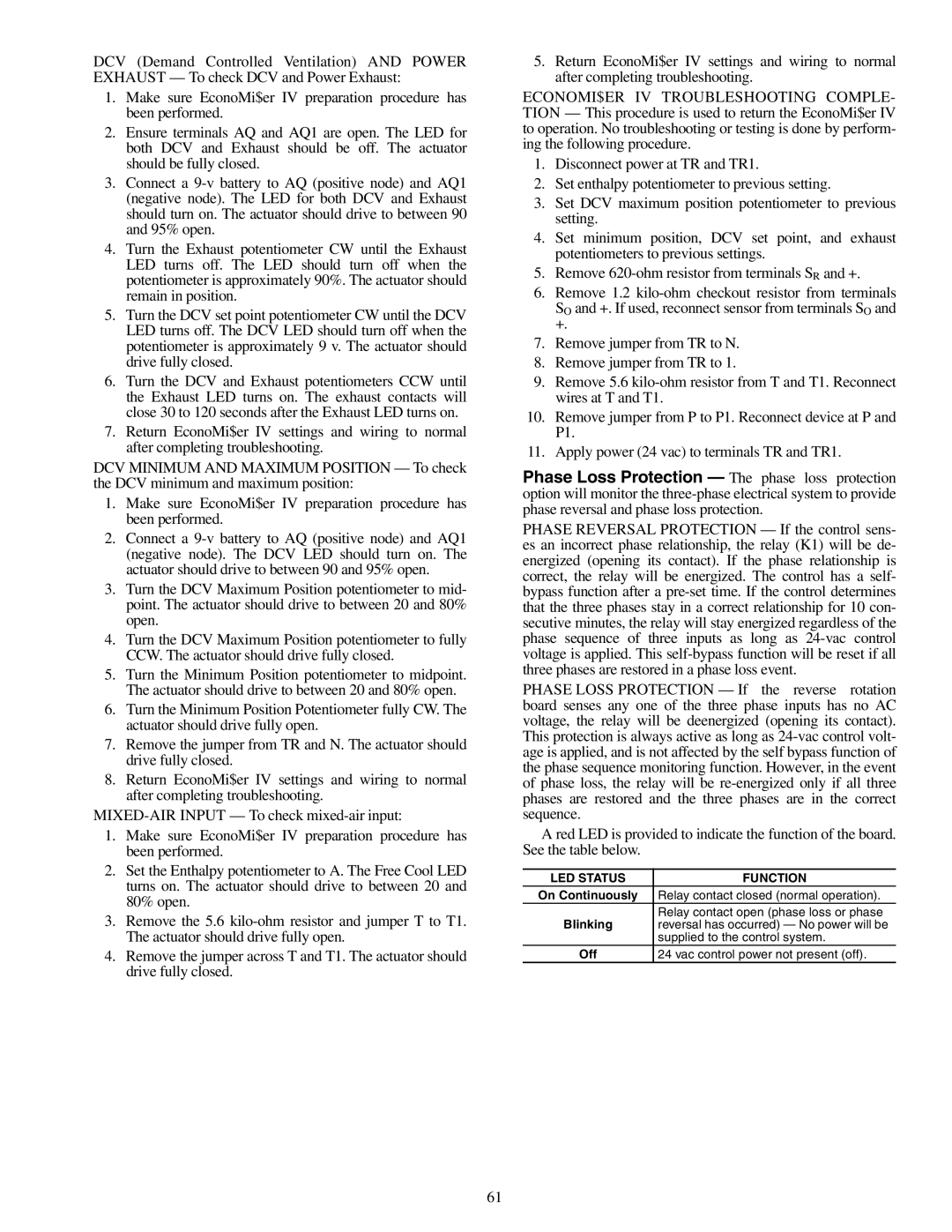
A red LED is provided to indicate the function of the board. See the table below.
LED STATUS | FUNCTION |
On Continuously | Relay contact closed (normal operation). |
Blinking | Relay contact open (phase loss or phase |
reversal has occurred) — No power will be | |
| supplied to the control system. |
Off | 24 vac control power not present (off). |
61