Table 30 — Belt Tension Adjustment
|
|
|
|
| BELT TENSION (lb) |
|
|
| ||
48PG | VOLTAGE |
|
|
| Unit Model Number Position 10 |
|
|
| ||
|
| A,J | B,K | C,L | D,M | E,N |
| F,P | G,Q | H,R |
| 230 | 4.8 | 5.1 | 5.6 | 4.5 | NA |
| 4.7 | 5.0 | 5.5 |
20 | 460 | 4.8 | 5.1 | 5.6 | 4.5 | NA |
| 4.7 | 5.0 | 5.5 |
| 575 | 5.3 | 5.1 | 5.6 | 4.5 | NA |
| 5.2 | 5.0 | 5.5 |
| 230 | 4.8 | 5.1 | 5.6 | 4.5 | NA |
| 4.7 | 5.0 | 5.5 |
24 | 460 | 4.8 | 5.1 | 5.6 | 4.5 | NA |
| 4.7 | 5.0 | 5.5 |
| 575 | 5.3 | 5.1 | 5.6 | 4.5 | NA |
| 5.2 | 5.0 | 5.5 |
| 230 | 4.5 | 5.4 | 5.9 | 4.5 | 4.5 |
| 5.4 | 5.9 | 4.5 |
28 | 460 | 4.5 | 5.4 | 5.9 | 4.5 | 4.5 |
| 5.4 | 5.9 | 4.5 |
| 575 | 4.5 | 5.4 | 5.9 | 4.5 | 4.5 |
| 5.4 | 5.9 | 4.5 |
Condenser-Fan Adjustment (Fig. 35)
1.Shut off unit power supply.
2.Remove
3.Adjust fan height as shown in Fig. 35.
4.Tighten setscrews and replace
5.Turn on power to unit.
Fig. 35 — Condenser-Fan Adjustment
Verify Sensor Performance — Using an ohmmeter and a thermometer, compare measured temperature to the resistance shown in Table 31.
Table 31 — Sensor Temperature/Resistance Values
TEMPERATURE (F) | RESISTANCE (ohms) |
200,250 | |
100,680 | |
53,010 | |
29,091 | |
14 | 16,590 |
32 | 9,795 |
50 | 5,970 |
68 | 3,747 |
77 | 3,000 |
86 | 2,416 |
104 | 1,597 |
122 | 1,080 |
140 | 746 |
158 | 525 |
176 | 376 |
185 | 321 |
194 | 274 |
212 | 203 |
230 | 153 |
248 | 116 |
257 | 102 |
266 | 89 |
284 | 70 |
302 | 55 |
Economizer Operation During Power Fail- ure — Dampers have a spring return. In event of power fail- ure, dampers will return to fully closed position until power is restored. Do not manually operate damper motor.
Evacuation — Proper evacuation of the system will re- move noncondensables and ensure a tight, dry system before charging. Evacuate from both high and low side ports. Never use the system compressor as a vacuum pump. Refrigerant tubes and indoor coil should be evacuated to 500 microns. Always break a vacuum with dry nitrogen. The two possible methods are the deep vacuum method and the triple evacuation method
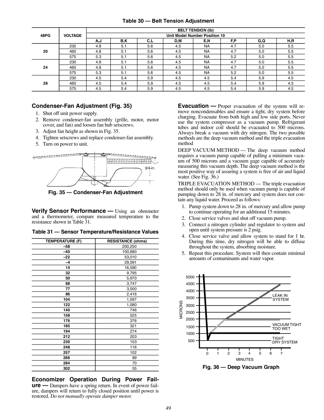
DEEP VACUUM METHOD — The deep vacuum method requires a vacuum pump capable of pulling a minimum vacu- um of 500 microns and a vacuum gage capable of accurately measuring this vacuum depth. The deep vacuum method is the most positive way of assuring a system is free of air and liquid water. (See Fig. 36.)
TRIPLE EVACUATION METHOD — The triple evacuation method should only be used when vacuum pump is capable of pumping down to 28 in. of mercury and system does not con- tain any liquid water. Proceed as follows:
1.Pump system down to 28 in. of mercury and allow pump to continue operating for an additional 15 minutes.
2.Close service valves and shut off vacuum pump.
3.Connect a nitrogen cylinder and regulator to system and open until system pressure is 2 psig.
4.Close service valve and allow system to stand for 1 hr. During this time, dry nitrogen will be able to diffuse throughout the system, absorbing moisture.
5.Repeat this procedure. System will then contain minimal amounts of contaminants and water vapor.
| 5000 |
|
|
|
|
|
|
|
| 4500 |
|
|
|
|
|
|
|
| 4000 |
|
|
|
|
|
|
|
| 3500 |
|
|
|
|
|
| LEAK IN |
MICRONS |
|
|
|
|
|
| SYSTEM | |
|
|
|
|
|
|
| ||
3000 |
|
|
|
|
|
|
| |
2500 |
|
|
|
|
|
|
| |
2000 |
|
|
|
|
|
|
| |
|
|
|
|
|
|
|
| |
| 1500 |
|
|
|
|
|
| VACUUM TIGHT |
|
|
|
|
|
|
| TOO WET | |
|
|
|
|
|
|
|
| |
| 1000 |
|
|
|
|
|
|
|
| 500 |
|
|
|
|
|
| TIGHT |
|
|
|
|
|
|
| DRY SYSTEM | |
|
|
|
|
|
|
|
| |
| 0 | 1 | 2 | 3 | 4 | 5 | 6 | 7 |
|
|
|
| MINUTES |
|
|
| |
Fig. 36 — Deep Vacuum Graph
49