3.Use the Up/Down button to select the preset number. See Table 29.
4.Press Enter to lock in the selection.
5.Press Mode to exit and resume normal operation.
outside air. The design should produce an air temperature somewhat near room conditions to prevent reheat of the air mixture. The energy recovery device should be interlocked with the heat to turn off the device when in the heat mode.
The custom settings of the CO2 sensor can be changed any- time after the sensor is energized. Follow the steps below to change the
1.Press Clear and Mode buttons. Hold at least 5 seconds until the sensor enters the Edit mode.
2.Press Mode twice. The STDSET Menu will appear.
3.Use the Up/Down button to toggle to the NONSTD menu and press Enter.
4.Use the Up/Down button to toggle through each of the nine variables, starting with Altitude, until the desired setting is reached.
5.Press Mode to move through the variables.
6.Press Enter to lock in the selection, then press Mode to continue to the next variable.
Dehumidification of Fresh Air with DCV Control — Infor- mation from ASHRAE (American Society of Heating, Refrigeration, and Air Conditioning Engineers) indicates that the largest humidity load on any zone is the fresh air intro- duced. For some applications, a device such as a 62AQ energy recovery unit is added to reduce the moisture content of the fresh air being brought into the building when the enthalpy is high. In most cases, the normal heating and cooling processes are more than adequate to remove the humidity loads for most commercial applications.
This makes the control of the of the dehumidification device simple when using the enthalpy or differential enthalpy sensor. The enthalpy sensor or differential enthalpy sensor is installed on the equipment to determine economizer operation. The high enthalpy signal from the enthalpy sensor or differential enthalpy sensor can be used to turn on the outdoor air moisture removal device any time fresh air is required for the space.
The energy recovery device should be sized for maximum latent and sensible conditioning at maximum ventilation on a design day. A calculation for
Operating Sequence
COOLING, UNITS WITHOUT ECONOMIZER — When the thermostat calls for one stage of cooling, Y1 and G are en- ergized. The
If more cooling is required, the thermostat will call for a second stage of cooling, energizing Y2. This will allow relay CR1 to energize, which in turn energizes the compressor contactor (C.C1 on
HEATING, UNITS WITHOUT ECONOMIZER NOTE: The
When the thermostat calls for heating, power is sent to W on the IGC (integrated gas unit controller) board. An LED
If the burners do not light, there is a
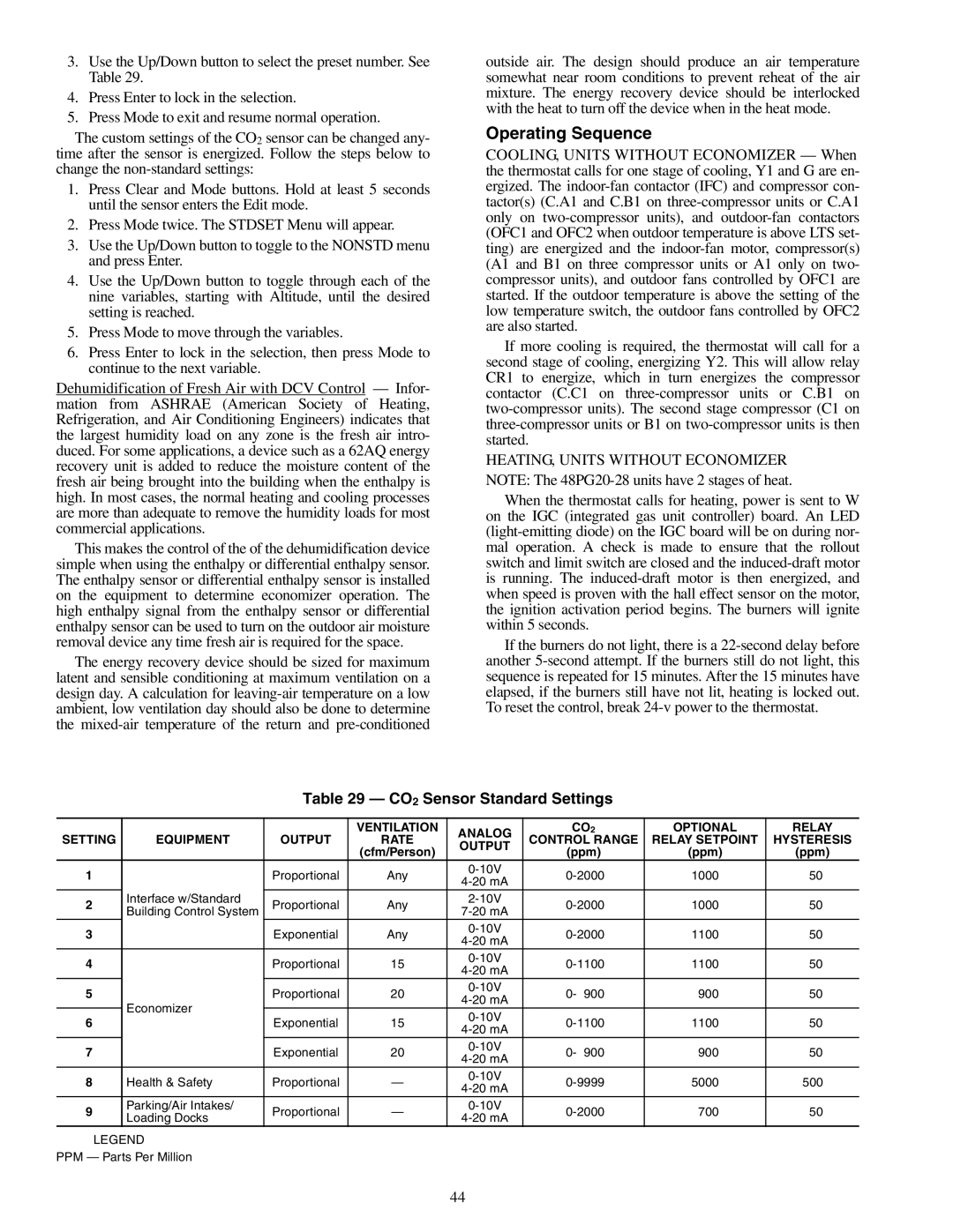
Table 29 — CO2 Sensor Standard Settings
|
|
| VENTILATION | ANALOG | CO2 | OPTIONAL | RELAY | |
SETTING | EQUIPMENT | OUTPUT | RATE | CONTROL RANGE | RELAY SETPOINT | HYSTERESIS | ||
OUTPUT | ||||||||
|
|
| (cfm/Person) | (ppm) | (ppm) | (ppm) | ||
|
|
|
| |||||
1 |
| Proportional | Any | 1000 | 50 | |||
| ||||||||
|
|
|
|
|
|
| ||
2 | Interface w/Standard | Proportional | Any | 1000 | 50 | |||
Building Control System | ||||||||
|
|
|
|
|
| |||
3 |
| Exponential | Any | 1100 | 50 | |||
| ||||||||
|
|
|
|
|
|
| ||
4 |
| Proportional | 15 | 1100 | 50 | |||
| ||||||||
|
|
|
|
|
|
| ||
5 |
| Proportional | 20 | 0- 900 | 900 | 50 | ||
| ||||||||
| Economizer |
|
|
|
|
| ||
6 | Exponential | 15 | 1100 | 50 | ||||
| ||||||||
| ||||||||
|
|
|
|
|
|
| ||
7 |
| Exponential | 20 | 0- 900 | 900 | 50 | ||
| ||||||||
|
|
|
|
|
|
| ||
8 | Health & Safety | Proportional | — | 5000 | 500 | |||
|
|
|
|
|
|
| ||
9 | Parking/Air Intakes/ | Proportional | — | 700 | 50 | |||
Loading Docks | ||||||||
|
|
|
|
|
|
LEGEND
PPM — Parts Per Million
44