Manuals
/
Carrier
/
Household Appliance
/
Heating System
Carrier
48PG20-28
specifications
Roof Curb Details
Models:
48PG20-28
1
3
64
64
Download
64 pages
4.71 Kb
1
2
3
4
5
6
7
8
Troubleshooting
Install
Charging Chart 48PG20
IGC Board LED Alarm Codes
Field Power Wiring Connections
Dimension
Belt Tension Adjustment
CO2 Sensor Standard Settings
Checklist
Service
Page 3
Image 3
3
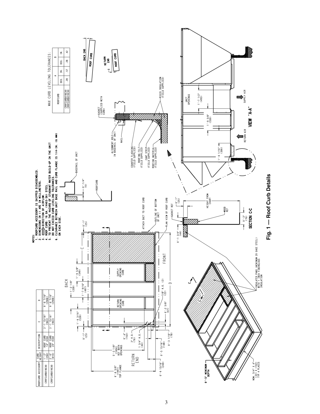
Fig. 1 — Roof Curb Details
Page 2
Page 4
Page 3
Image 3
Page 2
Page 4
Contents
Installation, Start-Up and Service Instructions
Provide Unit Support
Installation
Roof Curb Details
Shipping Rail Removal
Base Unit Dimensions
Compressor
Physical Data
Fan Motor and Drive Data Vertical Supply/Return
Fan Motor and Drive Data Horizontal Supply/Return
Alignment Hole Details
Make Unit Duct Connections
Concentric Duct Details
Install Flue Hood and Inlet Hood
Condensate Drain Details
Make Electrical Connections
Field Power Wiring Connections
Supply Optional Hacr Size
Supply Optional Hacr Size Voltage Breaker
Outdoor-Air Hood Details
Outdoor-Air Hood Assembled
Power Exhaust or Barometric Relief Damper Mounting Details
PRE-START-UP
Fan Performance 48PGD20 Vertical Supply/Return Units
Fan Performance 48PGE20 Vertical Supply/Return Units
8500 940
Fan Performance 48PGF20 Vertical Supply/Return Units
Fan Performance 48PGD24 Vertical Supply/Return Units
Fan Performance 48PGE24 Vertical Supply/Return Units
500 940
Fan Performance 48PGF24 Vertical Supply/Return Units
1310 11.76 1342 12.33 11,500
Fan Performance 48PGD28 Vertical Supply/Return Units
10,500
11,000
1309 1341 10.09 500
Fan Performance 48PGE28 Vertical Supply/Return Units
1327 11.47 11,000
1304 000
Fan Performance 48PGF28 Vertical Supply/Return Units
Fan Performance 48PGD20 Horizontal Supply and Return Units
Fan Performance 48PGE20 Horizontal Supply and Return Units
Fan Performance 48PGF20 Horizontal Supply and Return Units
Fan Performance 48PGD24 Horizontal Supply and Return Units
Fan Performance 48PGE24 Horizontal Supply and Return Units
1354 1391 000 1381 500 10,000
Fan Performance 48PGF24 Horizontal Supply and Return Units
1328 10.37 1358 10.87 10,000
Fan Performance 48PGD28 Horizontal Supply and Return Units
1308 1340 10.08 500
Fan Performance 48PGE28 Horizontal Supply and Return Units
General Notes for FAN Performance Data Tables
Fan Performance 48PGF28 Horizontal Supply and Return Units
Power Exhaust Fan Performance 48PG20-28
Evaporator Fan Motor Specifications
Operation Air Quantity Limits
Evaporator Fan Motor Specifications
Fan Rpm at Motor Pulley Settings
Accessory/FIOP Static Pressure in. wg* 48PG20-28
EconoMi$er IV Sensor Usage
EconoMi$er IV Wiring
Enthalpy Changeover Set Points
Page
Operating Sequence
CO2 Sensor Standard Settings
Subcooler Operation
Service
Removing Heat Exchanger Ceramic
Lubrication
Evaporator-Fan Motor Adjustment
Unit Model Number Position
Condenser-Fan Adjustment Fig
Belt Tension Adjustment
Sensor Temperature/Resistance Values
Charging Chart 48PG20
Gas Valve Adjustment
Gas Valve
Altitude Compensation
Protective Devices
Typical Low Voltage Control Schematic
Typical Power Schematic
Typical Component Arrangement 48PG20,24
Typical Component Arrangement 48PG28
Cooling Service Analysis
Troubleshooting
Burners Will Not Ignite
Gas Heating Service Analysis
IGC Control Heating and Cooling
Flashes
EconoMi$er IV Troubleshooting
IGC Board LED Alarm Codes
Flash
LED Status Function
Copyright 2005 Carrier Corporation
Page
Unit START-UP Checklist
Top
Page
Image
Contents