Refrigerant Charge — Amount of refrigerant charge is listed on unit nameplate. Refer to Carrier GTAC II; Module 5; Charging, Recovery, Recycling, and Reclamation section for charging methods and procedures. Unit panels must be in place when unit is operating during charging procedure.
Puron®
This system uses Puron refrigerant which has higher pressures than
NOTE: Do not use recycled refrigerant as it may contain contaminants.
NO CHARGE — Use standard evacuating techniques. After evacuating system, weigh in the specified amount of refriger- ant (refer to unit nameplate).
LOW CHARGE COOLING — Using cooling charging chart (see Fig.
TO USE THE COOLING CHARGING CHART — Use the above temperature and pressure readings, and find the intersec- tion point on the cooling charging chart. If intersection point on chart is above line, add refrigerant. If intersection point on chart is below line, carefully recover some of the charge. Re- check suction pressure as charge is adjusted.
NOTE:
The TXV (thermostatic expansion valve) is set to maintain between 10 and 15 degrees of superheat at the compressors. The valves are factory set and cannot be adjusted. Do not use a TXV designed for use with
PURON REFRIGERANT — Puron refrigerant operates at 50 to 70 percent higher pressures than
Fig. 37 — Charging Chart — 48PG20 |
Fig. 38 — Charging Chart — 48PG24 |
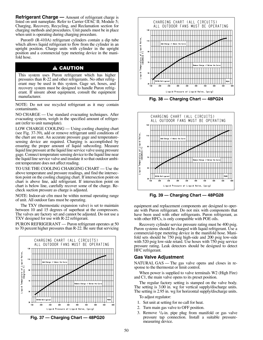
Fig. 39 — Charging Chart — 48PG28 |
equipment and replacement components are designed to oper- ate with Puron refrigerant. Do not mix with components that have been used with other refrigerants. Puron refrigerant, as with other HFCs, is only compatible with POE oils.
Recovery cylinder service pressure rating must be 400 psig. Puron systems should be charged with liquid refrigerant. Use a
Gas Valve Adjustment
NATURAL GAS — The gas valve opens and closes in re- sponse to the thermostat or limit control.
When power is supplied to valve terminals W2 (High Fire) and C1, the main valve opens to its preset position.
The regular factory setting is stamped on the valve body. The setting is 3.00 in. wg for vertical supply/discharge units. The setting is 2.95 in. wg for horizontal supply/discharge units.
To adjust regulator:
1.Set unit at setting for no call for heat.
2.Turn main gas valve to OFF position.
3.Remove
50