Condenser Fans and Motors — Condenser fans and motors are factory set. Refer to
NOTE: For units with
Gas Heat — Verify gas pressures before turning on heat as follows:
1.Turn off
2.Connect pressure gage to supply gas tap, located on field- supplied manual shutoff valve (see Fig. 14).
3.Connect pressure gage to manifold pressure tap.
4.Turn on
5.After the unit has run for several minutes, verify the sup- ply gas pressure is between 5.5 in. wg to 13.0 in. wg, and the manifold pressure is 2.95 in. wg on horizontal dis- charge applications and 3.00 on vertical discharge appli- cations. If manifold pressure must be adjusted, refer to Gas Valve Adjustment section.
NOTE: Supply gas pressure must not exceed 13.0 in. wg.
6.Set thermostat to OFF.
7.Remove jumper wire if the unit will be operating under thermostat mode.
8.Return thermostat to desired set point.
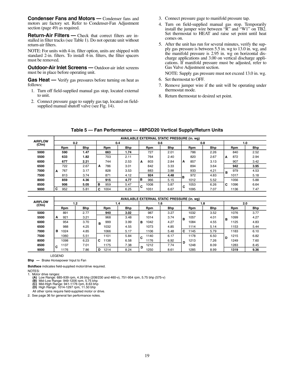
Table 5 — Fan Performance — 48PGD20 Vertical Supply/Return Units
AIRFLOW |
|
|
|
|
|
|
| AVAILABLE EXTERNAL STATIC PRESSURE (in. wg) |
|
|
|
|
| |||||||
|
| 0.2 |
| 0.4 |
|
| 0.6 |
|
| 0.8 |
|
|
| 1.0 | ||||||
(Cfm) |
|
|
|
|
|
|
|
|
|
| ||||||||||
|
| Rpm |
| Bhp |
| Rpm |
| Bhp |
| Rpm |
| Bhp |
| Rpm |
| Bhp |
| Rpm |
| Bhp |
5000 |
| 590 |
| 1.47 |
| 663 |
| 1.74 |
| 727 |
| 2.01 |
| 786 |
| 2.26 |
| 840 |
| 2.52 |
5500 |
| 633 |
| 1.82 |
| 703 |
| 2.11 |
| 764 |
| 2.40 |
| 820 |
| 2.67 | A | 872 |
| 2.94 |
6000 |
| 677 |
| 2.21 |
| 744 |
| 2.53 | A | 803 |
| 2.84 | A | 857 |
| 3.13 |
| 907 |
| 3.42 |
6500 |
| 722 |
| 2.67 | A | 786 |
| 3.01 |
| 842 |
| 3.33 |
| 894 |
| 3.64 |
| 942 |
| 3.95 |
7000 | A | 767 |
| 3.17 |
| 828 |
| 3.53 |
| 883 |
| 3.88 |
| 933 |
| 4.21 | B | 979 |
| 4.53 |
7500 |
| 813 |
| 3.74 |
| 871 |
| 4.12 |
| 924 |
| 4.48 | B | 972 |
| 4.83 | 1017 |
| 5.18 | |
|
|
|
|
|
|
|
|
| ||||||||||||
8000 |
| 859 |
| 4.36 |
| 915 |
| 4.77 | B | 966 |
| 5.15 | 1012 |
| 5.52 |
| 1056 |
| 5.88 | |
|
|
|
|
|
|
|
|
| ||||||||||||
8500 |
| 906 |
| 5.05 | B | 959 |
| 5.47 | C | 1008 |
| 5.87 | C | 1053 |
| 6.26 | C | 1096 |
| 6.64 |
9000 | C | 952 |
| 5.81 | C | 1004 |
| 6.25 | 1051 |
| 6.67 | 1095 |
| 7.07 |
| 1136 |
| 7.47 | ||
|
|
|
|
|
|
|
| |||||||||||||
|
|
|
|
|
|
|
|
|
|
|
|
|
| |||||||
AIRFLOW |
|
|
|
|
|
|
| AVAILABLE EXTERNAL STATIC PRESSURE (in. wg) |
|
|
|
|
| |||||||
|
| 1.2 |
| 1.4 |
|
| 1.6 |
|
| 1.8 |
|
|
| 2.0 | ||||||
(Cfm) |
|
|
|
|
|
|
|
|
|
| ||||||||||
|
| Rpm |
| Bhp |
| Rpm |
| Bhp |
| Rpm |
| Bhp |
| Rpm |
| Bhp |
| Rpm |
| Bhp |
5000 |
| 891 |
| 2.77 |
| 940 |
| 3.02 |
| 987 |
| 3.27 |
| 1032 |
| 3.52 |
| 1076 |
| 3.77 |
5500 | A | 921 |
| 3.21 |
| 968 |
| 3.48 |
| 1014 |
| 3.74 | B | 1057 |
| 4.01 | B | 1099 |
| 4.27 |
6000 |
| 954 |
| 3.70 | B | 999 |
| 3.99 | B | 1042 |
| 4.27 | 1084 |
| 4.55 | 1125 |
| 4.83 | ||
|
|
|
|
|
|
|
| |||||||||||||
6500 |
| 988 |
| 4.25 | 1032 |
| 4.55 |
| 1073 |
| 4.85 |
| 1114 |
| 5.14 |
| 1153 |
| 5.44 | |
|
|
|
|
|
|
|
|
|
| |||||||||||
7000 | B | 1024 |
| 4.85 |
| 1066 |
| 5.17 |
| 1106 |
| 5.48 | C | 1145 |
| 5.79 |
| 1183 |
| 6.10 |
7500 |
| 1060 |
| 5.51 |
| 1101 |
| 5.84 | C | 1140 |
| 6.17 |
| 1178 |
| 6.50 | D | 1215 |
| 6.82 |
8000 |
| 1098 |
| 6.23 | C | 1138 |
| 6.58 | 1176 |
| 6.92 | D | 1213 |
| 7.26 | 1249 |
| 7.60 | ||
|
|
|
|
|
|
|
| |||||||||||||
8500 | C | 1137 |
| 7.01 |
| 1175 |
| 7.38 | D | 1212 |
| 7.74 | 1248 |
| 8.09 |
| 1283 |
| 8.45 | |
|
|
|
|
|
|
|
| |||||||||||||
9000 | 1176 |
| 7.86 | D | 1214 |
| 8.24 | 1250 |
| 8.61 |
| 1285 |
| 8.99 |
| 1319 |
| 9.36 | ||
|
|
|
|
|
|
|
|
| ||||||||||||
LEGEND
Bhp — Brake Horsepower Input to Fan
Boldface indicates
NOTES:
1.Motor drive ranges:
(A)Low Range:
(B)
(C)
(D)High Range:
All other rpms require
2. See page 36 for general fan performance notes.
19