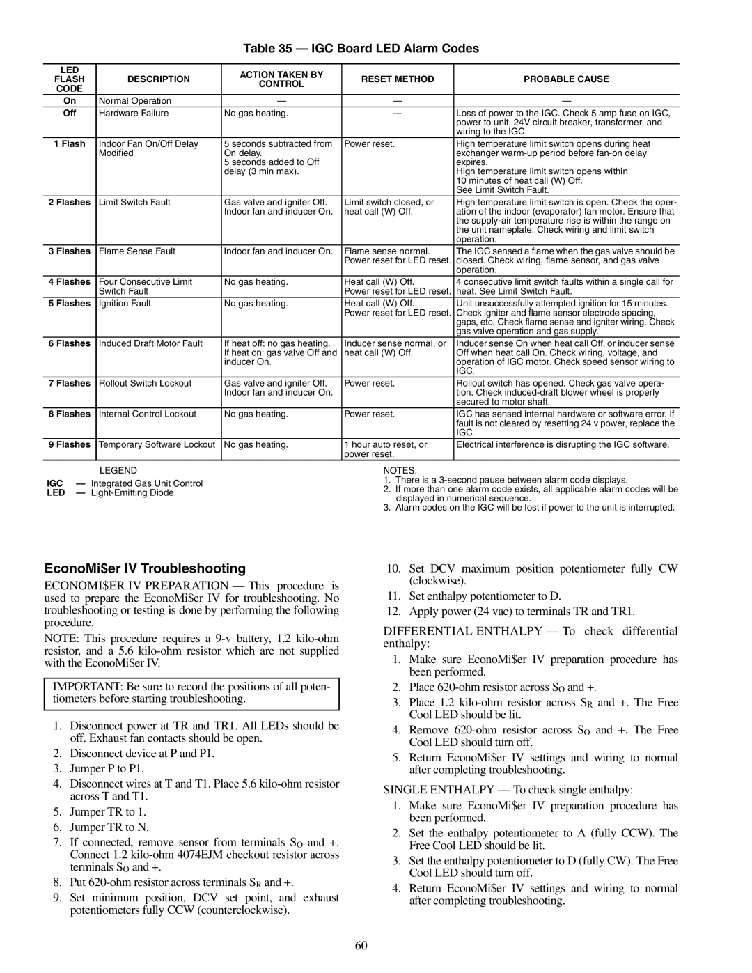
Table 35 — IGC Board LED Alarm Codes
LED |
| ACTION TAKEN BY |
|
| |
FLASH | DESCRIPTION | RESET METHOD | PROBABLE CAUSE | ||
CONTROL | |||||
CODE |
|
|
| ||
|
|
|
| ||
On | Normal Operation | — | — | — | |
Off | Hardware Failure | No gas heating. | — | Loss of power to the IGC. Check 5 amp fuse on IGC, | |
|
|
|
| power to unit, 24V circuit breaker, transformer, and | |
|
|
|
| wiring to the IGC. | |
1 Flash | Indoor Fan On/Off Delay | 5 seconds subtracted from | Power reset. | High temperature limit switch opens during heat | |
| Modified | On delay. |
| exchanger | |
|
| 5 seconds added to Off |
| expires. | |
|
| delay (3 min max). |
| High temperature limit switch opens within | |
|
|
|
| 10 minutes of heat call (W) Off. | |
|
|
|
| See Limit Switch Fault. | |
2 Flashes | Limit Switch Fault | Gas valve and igniter Off. | Limit switch closed, or | High temperature limit switch is open. Check the oper- | |
|
| Indoor fan and inducer On. | heat call (W) Off. | ation of the indoor (evaporator) fan motor. Ensure that | |
|
|
|
| the | |
|
|
|
| the unit nameplate. Check wiring and limit switch | |
|
|
|
| operation. | |
3 Flashes | Flame Sense Fault | Indoor fan and inducer On. | Flame sense normal. | The IGC sensed a flame when the gas valve should be | |
|
|
| Power reset for LED reset. | closed. Check wiring, flame sensor, and gas valve | |
|
|
|
| operation. | |
4 Flashes | Four Consecutive Limit | No gas heating. | Heat call (W) Off. | 4 consecutive limit switch faults within a single call for | |
| Switch Fault |
| Power reset for LED reset. | heat. See Limit Switch Fault. | |
5 Flashes | Ignition Fault | No gas heating. | Heat call (W) Off. | Unit unsuccessfully attempted ignition for 15 minutes. | |
|
|
| Power reset for LED reset. | Check igniter and flame sensor electrode spacing, | |
|
|
|
| gaps, etc. Check flame sense and igniter wiring. Check | |
|
|
|
| gas valve operation and gas supply. | |
6 Flashes | Induced Draft Motor Fault | If heat off: no gas heating. | Inducer sense normal, or | Inducer sense On when heat call Off, or inducer sense | |
|
| If heat on: gas valve Off and | heat call (W) Off. | Off when heat call On. Check wiring, voltage, and | |
|
| inducer On. |
| operation of IGC motor. Check speed sensor wiring to | |
|
|
|
| IGC. | |
7 Flashes | Rollout Switch Lockout | Gas valve and igniter Off. | Power reset. | Rollout switch has opened. Check gas valve opera- | |
|
| Indoor fan and inducer On. |
| tion. Check | |
|
|
|
| secured to motor shaft. | |
8 Flashes | Internal Control Lockout | No gas heating. | Power reset. | IGC has sensed internal hardware or software error. If | |
|
|
|
| fault is not cleared by resetting 24 v power, replace the | |
|
|
|
| IGC. | |
9 Flashes | Temporary Software Lockout | No gas heating. | 1 hour auto reset, or | Electrical interference is disrupting the IGC software. | |
|
|
| power reset. |
|
LEGEND
IGC — Integrated Gas Unit Control
LED —
NOTES:
1.There is a
2.If more than one alarm code exists, all applicable alarm codes will be displayed in numerical sequence.
3.Alarm codes on the IGC will be lost if power to the unit is interrupted.
EconoMi$er IV Troubleshooting
ECONOMI$ER IV PREPARATION — This procedure is used to prepare the EconoMi$er IV for troubleshooting. No troubleshooting or testing is done by performing the following procedure.
NOTE: This procedure requires a
IMPORTANT: Be sure to record the positions of all poten- tiometers before starting troubleshooting.
1.Disconnect power at TR and TR1. All LEDs should be off. Exhaust fan contacts should be open.
2.Disconnect device at P and P1.
3.Jumper P to P1.
4.Disconnect wires at T and T1. Place 5.6
5.Jumper TR to 1.
6.Jumper TR to N.
7.If connected, remove sensor from terminals SO and +. Connect 1.2
8.Put
9.Set minimum position, DCV set point, and exhaust potentiometers fully CCW (counterclockwise).
10.Set DCV maximum position potentiometer fully CW (clockwise).
11.Set enthalpy potentiometer to D.
12.Apply power (24 vac) to terminals TR and TR1.
DIFFERENTIAL ENTHALPY — To check differential enthalpy:
1.Make sure EconoMi$er IV preparation procedure has been performed.
2.Place
3.Place 1.2
4.Remove
5.Return EconoMi$er IV settings and wiring to normal after completing troubleshooting.
SINGLE ENTHALPY — To check single enthalpy:
1.Make sure EconoMi$er IV preparation procedure has been performed.
2.Set the enthalpy potentiometer to A (fully CCW). The Free Cool LED should be lit.
3.Set the enthalpy potentiometer to D (fully CW). The Free Cool LED should turn off.
4.Return EconoMi$er IV settings and wiring to normal after completing troubleshooting.
60