|
|
|
|
| Deluxe D | |
22 |
|
|
|
|
| |
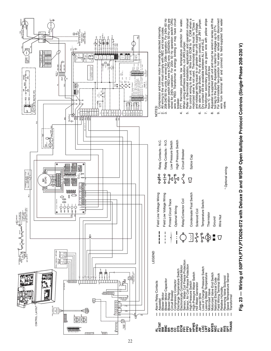
| LEGEND |
|
| NOTES: | ||
AL | — Alarm Relay Contacts | Field Line Voltage Wiring |
| |||
ASTAT | — Aquastat | Relay Contacts - N.C. | 1. | Compressor and blower motor thermally protected internally. | ||
| ||||||
BM | — Blower Motor | Field Low Voltage Wiring |
| 2. | All wiring to the unit must comply with NEC and local codes. | |
BMC | — Blower Motor Capacitor | Relay Contacts - N.O. | 3. | |||
| ||||||
BR | — Blower Relay | Printed Circuit Trace | Low Pressure Switch |
| operation switch RED wire to ORG wire. 2240240v 50 Hz units are | |
CB | — Circuit Breaker |
| wired for 240v operation. For 220v 50 Hz operation switch ORG | |||
|
| |||||
CC | — Compressor Contactor | Optional Wiring | High Pressure Switch |
| wire to RED. Transformer is energy limiting or may have circuit | |
DTS | — Discharge Temperature Switch |
|
| breaker. | ||
ECM | — Electronically Commutated Motor | Relay/Contactor Coil | Circuit Breaker | 4. | FP1 thermistor provides low temperature protection for water. | |
FP1 | — Sensor, Water Coil Freeze Protection |
| When using antifreeze solutions, cut JW3 jumper. | |||
|
|
| ||||
FP2 | — Sensor, Air Coil Freeze Protection |
|
| 5. | Refer to thermostat installation, application and operation manual | |
HP | — | Condensate Float Switch | Splice Cap |
| for control wiring to the unit. Wire from ECM to “Y” CXM when a | |
HPWS | — |
|
|
| motorized valve is not used. Thermostat wiring must be “Class 1” | |
HWG | — Hot Water Generator | Solenoid Coil |
|
| and volatage rating equal to or greater than unit supply voltage. | |
JW | — Jumper Wire |
|
| 6. | 24v alarm signal shown. For dry alarm contact, cut JW1 jumper. | |
LOC | — Loss of Charge Pressure Switch | Temperature Switch |
|
| Dry contact will be available between AL1 and AL2. | |
LWT | — Leaving Water Temperature | Thermistor |
| 7. | Transformer secondary ground via green wire with yellow stripe | |
MV | — Motorized Valve |
|
| from “C” terminal to control box | ||
MVES | — Motorized Valve End Switch | Ground |
| 8. | Aquastat is supplied with unit and must be wired in series with the | |
NEC | — National Electrical Code |
|
| hot leg to the pump. Aquastat is rated for voltages up to 277v. | ||
P1 | — Field Wiring Terminal Block | Wire Nut |
| 9. | For | |
RH | — Relative Humidity |
|
| wire from terminal W1 and connect to | ||
|
|
| ||||
RVS | — Reversing Valve Solenoid |
| * Optional wiring. |
| valve. | |
SPT | — Space Temperature Sensor |
|
|
| ||
|
|
|
| |||
TRANS | — Transformer |
|
|
|
| |