conform to the Class II temperature limitations described in the NEC.
Refer to unit wiring diagrams Fig.
Consult the unit wiring diagram located on the inside of the compressor access panel to ensure proper electrical hookup. The installing (or electrical) contractor must make the field connections when using
Operating voltage must be the same voltage and phase as shown in electrical data shown in Table 4.
Make all final electrical connections with a length of flexi- ble conduit to minimize vibration and sound transmission to the building.
POWER CONNECTION — Make line voltage connection by connecting the incoming line voltage wires to the line side of the compressor contactor terminal as shown in Fig. 25. See Table 4 for amperage ratings to provide correct wire and maximum overcurrent protection sizing.
SUPPLY VOLTAGE — Operating voltage to unit must be within voltage range indicated on unit nameplate.
On
% Voltage Imbalance
= 100 x | max voltage deviation from average voltage |
| average voltage |
Example: Supply voltage is
AB = 452 volts
BC = 464 volts
AC = 455 volts
Average Voltage = 452 + 464 + 455 3
=1371
3
= 457
Determine maximum deviation from average voltage:
(AB) 457 – 452 = 5 v (BC) 464 – 457 = 7 v (AC) 457 – 455 = 2 v
Maximum deviation is 7 v. Determine percent voltage imbalance.
% Voltage Imbalance = | 100 x | 7 |
457 | ||
= | 1.53% |
|
This amount of phase imbalance is satisfactory as it is below the maximum allowable 2%.
Operation on improper line voltage or excessive phase imbalance constitutes abuse and may cause damage to electri- cal components.
NOTE: If more than 2% voltage imbalance is present, contact your local electric utility.
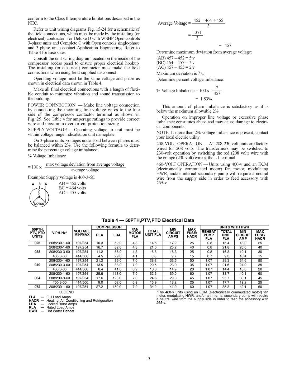
Table 4 — 50PTH,PTV,PTD Electrical Data
50PTH, |
| VOLTAGE | COMPRESSOR | FAN | TOTAL | MIN | MAX |
| UNITS WITH HWR |
| ||
PTV, PTD |
|
| MOTOR | CIRCUIT | FUSE/ | REHEAT | TOTAL | MIN | MAX | |||
MIN/MAX | RLA | LRA | UNIT FLA | PUMP | UNIT | CIRCUIT | FUSE/ | |||||
UNITS |
|
|
|
| FLA |
| AMPS | HACR | FLA | FLA | AMP | HACR |
|
|
|
|
|
|
|
|
| ||||
026 | 197/254 | 10.3 | 52.0 | 4.3 | 14.6 | 17.2 | 25 | 0.8 | 15.4 | 18.0 | 25 | |
| 197/254 | 16.7 | 82.0 | 4.3 | 21.0 | 25.2 | 40 | 0.8 | 21.8 | 26.0 | 40 | |
038 | 197/254 | 11.2 | 58.0 | 4.3 | 15.5 | 18.3 | 25 | 0.8 | 16.3 | 19.1 | 30 | |
| 414/506 | 4.5 | 29.0 | 4.1 | 8.6 | 9.7 | 15 | 0.7 | 9.3 | 10.4 | 15 | |
| 197/254 | 21.2 | 96.0 | 7.0 | 28.2 | 33.5 | 50 | 1.07 | 29.3 | 34.6 | 50 | |
049 | 197/254 | 13.5 | 88.0 | 7.0 | 20.5 | 23.9 | 35 | 1.07 | 21.6 | 24.9 | 35 | |
| 414/506 | 6.4 | 41.0 | 6.9 | 13.3 | 14.9 | 20 | 1.07 | 14.4 | 16.0 | 20 | |
| 197/254 | 25.6 | 118.0 | 7.0 | 32.6 | 39.0 | 60 | 1.07 | 33.7 | 40.1 | 60 | |
064 | 197/254 | 17.6 | 123.0 | 7.0 | 24.6 | 29.0 | 45 | 1.07 | 25.7 | 30.1 | 45 | |
| 414/506 | 9.0 | 62.0 | 6.9 | 15.9 | 18.2 | 25 | 1.07 | 17.7 | 19.2 | 25 | |
072 | 197/254 | 27.2 | 150.0 | 7.0 | 34.2 | 41.0 | 60 | 1.07 | 35.3 | 42.1 | 60 | |
| LEGEND |
FLA | — Full Load Amps |
HACR | — Heating, Air Conditioning and Refrigeration |
LRA | — Locked Rotor Amps |
RLA | — Rated Load Amps |
HWR | — Hot Water Reheat |
*The
13