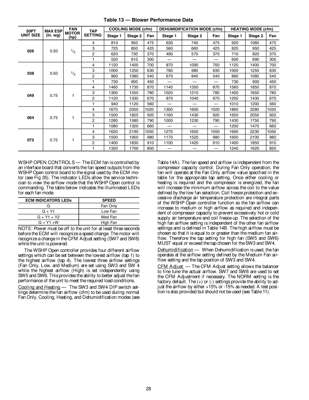
Table 13 — Blower Performance Data
50PT | MAX ESP | FAN | TAP | COOLING MODE (cfm) | DEHUMIDIFICATION MODE (cfm) | HEATING MODE (cfm) | |||||||
MOTOR |
|
|
|
|
|
|
|
|
| ||||
UNIT SIZE | (in. wg) | SETTING | Stage 1 | Stage 2 | Fan | Stage 1 | Stage 2 | Fan | Stage 1 | Stage 2 | Fan | ||
|
| (hp) |
|
|
|
|
|
|
|
|
|
| |
|
|
| 4 | 810 | 950 | 475 | 630 | 740 | 475 | 920 | 1060 | 475 | |
026 | 0.50 | 1/2 | 3 | 725 | 850 | 425 | 560 | 660 | 425 | 825 | 950 | 425 | |
2 | 620 | 730 | 370 | 490 | 570 | 370 | 710 | 820 | 370 | ||||
|
|
| |||||||||||
|
|
| 1 | 520 | 610 | 300 | — | — | — | 600 | 690 | 300 | |
|
|
| 4 | 1120 | 1400 | 700 | 870 | 1090 | 700 | 1120 | 1400 | 700 | |
038 | 0.50 | 1/2 | 3 | 1000 | 1250 | 630 | 780 | 980 | 630 | 1000 | 1250 | 630 | |
2 | 860 | 1080 | 540 | 670 | 840 | 540 | 860 | 1080 | 540 | ||||
|
|
| |||||||||||
|
|
| 1 | 730 | 900 | 450 | — | — | — | 730 | 900 | 450 | |
|
|
| 4 | 1460 | 1730 | 870 | 1140 | 1350 | 870 | 1560 | 1850 | 870 | |
049 | 0.75 | 1 | 3 | 1300 | 1550 | 780 | 1020 | 1210 | 780 | 1400 | 1650 | 780 | |
2 | 1120 | 1330 | 670 | 870 | 1040 | 670 | 1200 | 1430 | 670 | ||||
|
|
| |||||||||||
|
|
| 1 | 940 | 1120 | 560 | — | — | — | 1010 | 1200 | 560 | |
|
|
| 4 | 1670 | 2050 | 1020 | 1300 | 1600 | 1020 | 1860 | 2280 | 1020 | |
064 | 0.75 | 1 | 3 | 1500 | 1825 | 920 | 1160 | 1430 | 920 | 1650 | 2050 | 920 | |
2 | 1280 | 1580 | 790 | 1000 | 1230 | 790 | 1430 | 1750 | 790 | ||||
|
|
| |||||||||||
|
|
| 1 | 1080 | 1320 | 660 | — | — | — | 1200 | 1470 | 660 | |
|
|
| 4 | 1620 | 2190 | 1050 | 1270 | 1650 | 1050 | 1690 | 2230 | 1050 | |
072 | 0.75 | 1 | 3 | 1500 | 1950 | 980 | 1170 | 1520 | 980 | 1600 | 2100 | 980 | |
2 | 1400 | 1830 | 910 | 1100 | 1420 | 910 | 1400 | 1850 | 910 | ||||
|
|
| |||||||||||
|
|
| 1 | 1320 | 1700 | 850 | — | — | — | 1240 | 1620 | 850 | |
WSHP OPEN CONTROLS — The ECM fan is controlled by an interface board that converts the fan speed outputs from the WSHP Open control board to the signal used by the ECM mo- tor (see Fig 35). The indicator LEDs allow the service techni- cian to view the airflow mode that the WSHP Open control is commanding. The table below indicates the illuminated LEDs for each fan mode.
ECM INDICATORS LEDs | SPEED |
G | Fan Only |
G + Y1 | Low Fan |
G + Y1 + Y2 | Med Fan |
G + Y1 +W | High Fan |
NOTE: Power must be off to the unit for at least three seconds before the ECM will recognize a speed change. The motor will recognize a change in the CFM Adjust setting (SW7 and SW8) while the unit is powered.
The WSHP Open controller provides four different airflow settings which can be set between the lowest airflow (tap 1) to the highest airflow (tap 4). The lowest three airflow settings (Fan Only, Low, and Medium) are set using SW3 and SW 4 while the highest airflow (High) is set independently using SW5 and SW6. This provides the ability to better adjust the fan performance of the unit to meet the required load conditions.
Cooling and Heating — The SW3 and SW4 DIP switch set- tings determine the fan airflow (cfm) to be used during normal Fan Only, Cooling, Heating, and Dehumidification modes (see
Table 14A). The fan speed and airflow is independent from the compressor capacity control. During Fan Only operation, the fan will operate at the Fan Only airflow value specified in the table for the appropriate tap setting. Once either cooling or heating is required and the compressor is energized, the fan will increase the minimum airflow across the coil to the value defined by the low fan selection. Coil freeze protection and ex- cessive discharge air temperature protection are integral parts of the WSHP Open controller function so the fan airflow can increase to medium or high airflow as required and indepen- dent of compressor capacity to prevent excessively hot or cold supply air temperature and coil
Dehumidification — When Dehumidification is used, the fan operates at the airflow setting defined by the Medium Fan air- flow setting and the tap position of SW3 and SW4.
CFM Adjust — The CFM Adjust setting allows the balancer to fine tune the actual airflow. SW7 and SW8 are used to set the CFM Adjustment if necessary. The NORM setting is the factory default. The (+) or
28