Boilerless Changeover Temperature — Switch 8 on S1 provides selection of boilerless changeover temperature set point. Select OFF for set point of 50 F or select ON for set point of 40 F.
If switch 8 is set for 50 F, then the compressor will be used for heating as long as the FP1 is above 50 F. The compressor will not be used for heating when the FP1 is below 50 F and the compressor will operates in emergency heat mode, staging on EH1 and EH2 to provide heat. If a thermal switch is being used instead of the FP1 thermistor, only the compressor will be used for heating mode when the FP1 terminals are closed. If the FP1 terminals are open, the compressor is not used and the control goes into emergency heat mode.
DIP SWITCH BANK 2 (S2) — This set of DIP switches is used to configure accessory relay options. See Fig. 16, 18, 20, 22, and 23.
Switches 1 to 3 — These DIP switches provide selection of Accessory 1 relay options. See Table 15A for DIP switch combinations.
Switches 4 to 6 — These DIP switches provide selection of Accessory 2 relay options. See Table 15B for DIP switch combinations.
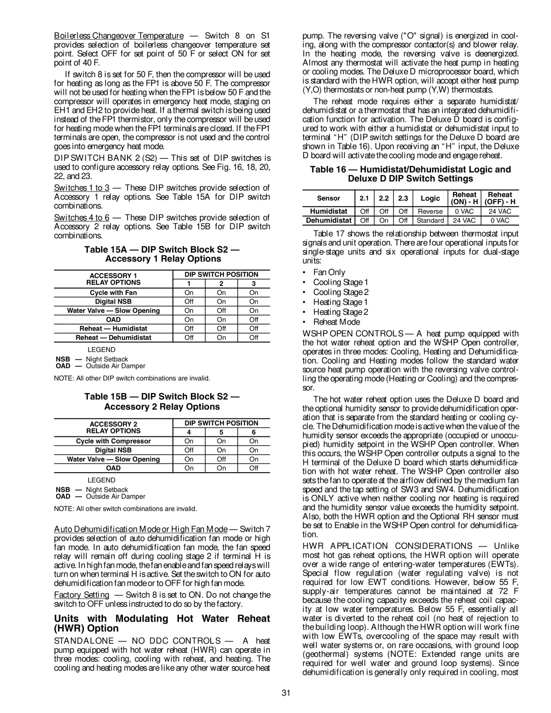
Table 15A — DIP Switch Block S2 —
Accessory 1 Relay Options
ACCESSORY 1 | DIP SWITCH POSITION | ||
RELAY OPTIONS | 1 | 2 | 3 |
Cycle with Fan | On | On | On |
Digital NSB | Off | On | On |
Water Valve — Slow Opening | On | Off | On |
OAD | On | On | Off |
Reheat — Humidistat | Off | Off | Off |
Reheat — Dehumidistat | Off | On | Off |
LEGEND
NSB — Night Setback
OAD — Outside Air Damper
NOTE: All other DIP switch combinations are invalid.
Table 15B — DIP Switch Block S2 —
Accessory 2 Relay Options
ACCESSORY 2 | DIP SWITCH POSITION | ||
RELAY OPTIONS | 4 | 5 | 6 |
Cycle with Compressor | On | On | On |
Digital NSB | Off | On | On |
Water Valve — Slow Opening | On | Off | On |
OAD | On | On | Off |
LEGEND
NSB — Night Setback
OAD — Outside Air Damper
NOTE: All other switch combinations are invalid.
Auto Dehumidification Mode or High Fan Mode — Switch 7 provides selection of auto dehumidification fan mode or high fan mode. In auto dehumidification fan mode, the fan speed relay will remain off during cooling stage 2 if terminal H is active. In high fan mode, the fan enable and fan speed relays will turn on when terminal H is active. Set the switch to ON for auto dehumidification fan mode or to OFF for high fan mode.
Factory Setting — Switch 8 is set to ON. Do not change the switch to OFF unless instructed to do so by the factory.
Units with Modulating Hot Water Reheat (HWR) Option
STANDALONE — NO DDC CONTROLS — A heat pump equipped with hot water reheat (HWR) can operate in three modes: cooling, cooling with reheat, and heating. The cooling and heating modes are like any other water source heat
pump. The reversing valve ("O" signal) is energized in cool- ing, along with the compressor contactor(s) and blower relay. In the heating mode, the reversing valve is deenergized. Almost any thermostat will activate the heat pump in heating or cooling modes. The Deluxe D microprocessor board, which is standard with the HWR option, will accept either heat pump (Y,O) thermostats or
The reheat mode requires either a separate humidistat/ dehumidistat or a thermostat that has an integrated dehumidifi- cation function for activation. The Deluxe D board is config- ured to work with either a humidistat or dehumidistat input to terminal “H” (DIP switch settings for the Deluxe D board are shown in Table 16). Upon receiving an “H” input, the Deluxe D board will activate the cooling mode and engage reheat.
Table 16 — Humidistat/Dehumidistat Logic and
Deluxe D DIP Switch Settings
Sensor | 2.1 | 2.2 | 2.3 | Logic | Reheat | Reheat | |
(ON) - H | (OFF) - H | ||||||
|
|
|
|
| |||
Humidistat | Off | Off | Off | Reverse | 0 VAC | 24 VAC | |
Dehumidistat | Off | On | Off | Standard | 24 VAC | 0 VAC |
Table 17 shows the relationship between thermostat input signals and unit operation. There are four operational inputs for
•Fan Only
•Cooling Stage 1
•Cooling Stage 2
•Heating Stage 1
•Heating Stage 2
•Reheat Mode
WSHP OPEN CONTROLS — A heat pump equipped with the hot water reheat option and the WSHP Open controller, operates in three modes: Cooling, Heating and Dehumidifica- tion. Cooling and Heating modes follow the standard water source heat pump operation with the reversing valve control- ling the operating mode (Heating or Cooling) and the compres- sor.
The hot water reheat option uses the Deluxe D board and the optional humidity sensor to provide dehumidification oper- ation that is separate from the standard heating or cooling cy- cle. The Dehumidification mode is active when the value of the humidity sensor exceeds the appropriate (occupied or unoccu- pied) humidity setpoint in the WSHP Open controller. When this occurs, the WSHP Open controller outputs a signal to the H terminal of the Deluxe D board which starts dehumidifica- tion with hot water reheat. The WSHP Open controller also sets the fan to operate at the airflow defined by the medium fan speed and the tap setting of SW3 and SW4. Dehumidification is ONLY active when neither cooling nor heating is required and the humidity sensor value exceeds the humidity setpoint. Also, both the HWR option and the Optional RH sensor must be set to Enable in the WSHP Open control for dehumidifica- tion.
HWR APPLICATION CONSIDERATIONS — Unlike most hot gas reheat options, the HWR option will operate over a wide range of
31