To wire the SPT sensor to the controller:
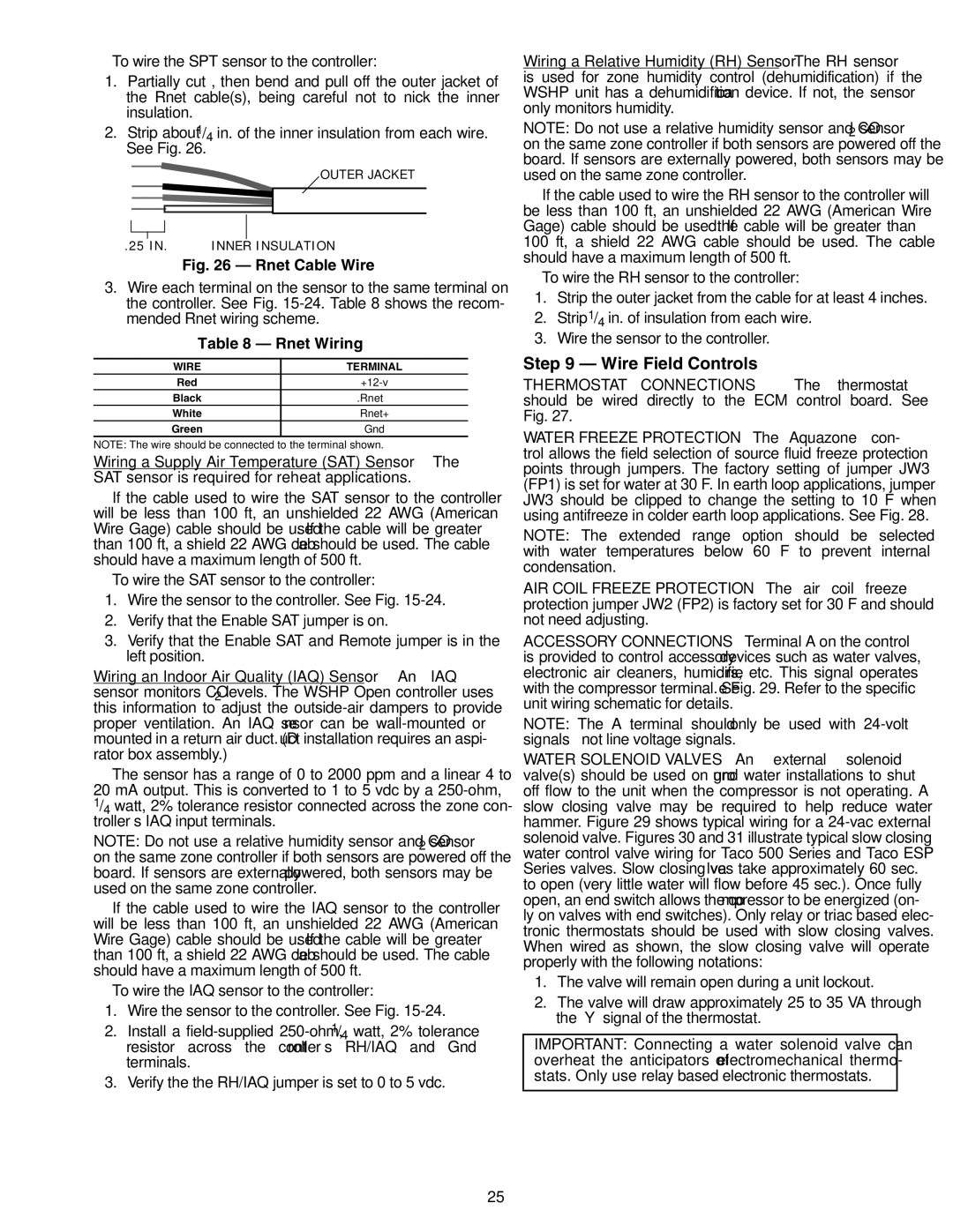
1.Partially cut , then bend and pull off the outer jacket of the Rnet cable(s), being careful not to nick the inner insulation.
2.Strip about 1/4 in. of the inner insulation from each wire. See Fig. 26.
OUTER JACKET
a50-8443
.25 IN. | INNER INSULATION |
Fig. 26 — Rnet Cable Wire
3.Wire each terminal on the sensor to the same terminal on the controller. See Fig.
Table 8 — Rnet Wiring
WIRE | TERMINAL |
Red | |
Black | .Rnet– |
White | Rnet+ |
Green | Gnd |
NOTE: The wire should be connected to the terminal shown.
Wiring a Supply Air Temperature (SAT) Sensor — The SAT sensor is required for reheat applications.
If the cable used to wire the SAT sensor to the controller will be less than 100 ft, an unshielded 22 AWG (American Wire Gage) cable should be used. If the cable will be greater than 100 ft, a shield 22 AWG cable should be used. The cable should have a maximum length of 500 ft.
To wire the SAT sensor to the controller:
1.Wire the sensor to the controller. See Fig.
2.Verify that the Enable SAT jumper is on.
3.Verify that the Enable SAT and Remote jumper is in the left position.
Wiring an Indoor Air Quality (IAQ) Sensor — An IAQ sensor monitors CO2 levels. The WSHP Open controller uses this information to adjust the
The sensor has a range of 0 to 2000 ppm and a linear 4 to
20 mA output. This is converted to 1 to 5 vdc by a
NOTE: Do not use a relative humidity sensor and CO2 sensor on the same zone controller if both sensors are powered off the board. If sensors are externally powered, both sensors may be used on the same zone controller.
If the cable used to wire the IAQ sensor to the controller will be less than 100 ft, an unshielded 22 AWG (American Wire Gage) cable should be used. If the cable will be greater than 100 ft, a shield 22 AWG cable should be used. The cable should have a maximum length of 500 ft.
To wire the IAQ sensor to the controller:
1.Wire the sensor to the controller. See Fig.
2.Install a
3.Verify the the RH/IAQ jumper is set to 0 to 5 vdc.
Wiring a Relative Humidity (RH) Sensor — The RH sensor is used for zone humidity control (dehumidification) if the WSHP unit has a dehumidification device. If not, the sensor only monitors humidity.
NOTE: Do not use a relative humidity sensor and CO2 sensor on the same zone controller if both sensors are powered off the board. If sensors are externally powered, both sensors may be used on the same zone controller.
If the cable used to wire the RH sensor to the controller will be less than 100 ft, an unshielded 22 AWG (American Wire Gage) cable should be used. If the cable will be greater than 100 ft, a shield 22 AWG cable should be used. The cable should have a maximum length of 500 ft.
To wire the RH sensor to the controller:
1.Strip the outer jacket from the cable for at least 4 inches.
2.Strip 1/4 in. of insulation from each wire.
3.Wire the sensor to the controller.
Step 9 — Wire Field Controls
THERMOSTAT CONNECTIONS — The thermostat should be wired directly to the ECM control board. See Fig. 27.
WATER FREEZE PROTECTION — The Aquazone™ con- trol allows the field selection of source fluid freeze protection points through jumpers. The factory setting of jumper JW3 (FP1) is set for water at 30 F. In earth loop applications, jumper JW3 should be clipped to change the setting to 10 F when using antifreeze in colder earth loop applications. See Fig. 28.
NOTE: The extended range option should be selected with water temperatures below 60 F to prevent internal condensation.
AIR COIL FREEZE PROTECTION — The air coil freeze protection jumper JW2 (FP2) is factory set for 30 F and should not need adjusting.
ACCESSORY CONNECTIONS — Terminal A on the control is provided to control accessory devices such as water valves, electronic air cleaners, humidifiers, etc. This signal operates with the compressor terminal. See Fig. 29. Refer to the specific unit wiring schematic for details.
NOTE: The A terminal should only be used with
WATER SOLENOID VALVES — An external solenoid valve(s) should be used on ground water installations to shut off flow to the unit when the compressor is not operating. A slow closing valve may be required to help reduce water hammer. Figure 29 shows typical wiring for a
1.The valve will remain open during a unit lockout.
2.The valve will draw approximately 25 to 35 VA through the “Y” signal of the thermostat.
IMPORTANT: Connecting a water solenoid valve can overheat the anticipators of electromechanical thermo- stats. Only use relay based electronic thermostats.
25