BM (ECM)
SW1 |
SW2 |
SW3 |
SW4
SW5
SW6
SW7
SW8
SW9
OFF ON
ECM
INTERFACE
BOARD
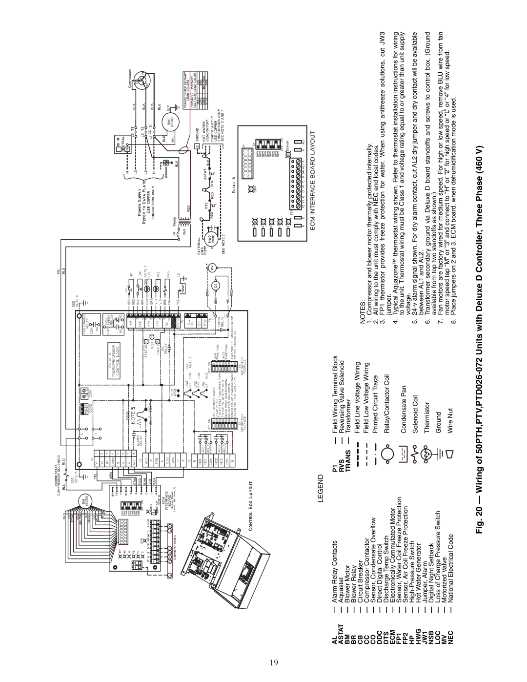
19
LEGEND
AL | — Alarm Relay Contacts | P1 | — Field Wiring Terminal Block | ||||||||||
ASTAT | — Aquastat | RVS | — Reversing Valve Solenoid | ||||||||||
BM | — Blower Motor | TRANS | — Transformer | ||||||||||
BR | — Blower Relay |
|
|
|
|
|
|
|
|
|
|
| Field Line Voltage Wiring |
CB | — Circuit Breaker |
|
|
|
|
|
|
|
|
|
|
| |
|
|
|
|
|
|
|
|
|
|
| Field Low Voltage Wiring | ||
CC | — Compressor Contactor |
|
|
|
|
|
|
|
|
|
|
| |
CO | — Sensor, Condensate Overflow |
|
|
|
|
|
|
|
|
|
|
| Printed Circuit Trace |
DDC | — Direct Digital Control |
|
|
|
|
|
|
|
|
|
|
|
|
DTS | — Discharge Temp Switch |
|
|
|
|
|
|
|
|
|
|
| Relay/Contactor Coil |
ECM | — Electronically Commutated Motor |
|
|
|
|
|
|
|
|
|
|
|
|
FP1 | — Sensor, Water Coil Freeze Protection |
|
|
|
|
|
|
|
|
|
|
| Condensate Pan |
|
|
|
|
|
|
|
|
|
|
| |||
FP2 | — Sensor, Air Coil Freeze Protection |
|
|
|
|
|
|
|
|
|
|
| |
|
|
|
|
|
|
|
|
|
|
| |||
HP | — |
|
|
|
|
|
|
|
|
|
|
| Solenoid Coil |
HWG | — Hot Water Generator |
|
|
|
|
|
|
|
|
|
|
| |
|
|
|
|
|
|
|
|
|
|
|
| ||
JW1 | — Jumper, Alarm |
|
|
|
|
|
|
|
|
|
|
| Thermistor |
NSB | — Digital Night Setback |
|
|
|
|
|
|
|
|
|
|
| |
|
|
|
|
|
|
|
|
|
|
|
| ||
|
|
|
|
|
|
|
|
|
|
|
| ||
LOC | — Loss of Charge Pressure Switch |
|
|
|
|
|
|
|
|
|
|
| Ground |
MV | — Motorized Valve |
|
|
|
|
|
|
|
|
|
|
| Wire Nut |
|
|
|
|
|
|
|
|
|
|
| |||
NEC | — National Electrical Code |
|
|
|
|
|
|
|
|
|
|
| |
BM
(ECM)
|
| J1 |
|
| Y |
W | R | S1 |
| CFM | |
|
| SW1 |
O |
|
|
|
|
| SW2 |
| |
G |
|
|
|
| SW3 |
| ||
|
|
|
|
|
| SW4 |
| |
|
|
|
|
|
| SW5 |
| |
Y2 | G |
|
|
|
| SW6 |
| |
|
|
|
|
|
| SW7 |
| |
|
|
|
|
|
| SW8 |
| |
Y1 | G |
|
|
|
| SW9 |
| |
|
|
|
|
| OFF | ON | ||
|
|
|
|
|
|
| ||
G | G | TB1 |
|
|
| G | DEHUM | |
|
|
|
|
|
|
|
| |
R | C | Y2 Y1 G | O | W | C | R DH AL1 A | A | AL1 |
ECM INTERFACE BOARD LAYOUT
NOTES:
1.Compressor and blower motor thermally protected internally.
2.All wiring to the unit must comply with NEC and local codes.
3.FP1 thermistor provides freeze protection for water. When using antifreeze solutions, cut JW3 jumper.
4.Typical Aquazone™ thermostat wiring shown. Refer to thermostat installation instructions for wiring to the unit. Thermostat wiring must be Class 1 and voltage rating equal to or greater than unit supply voltage.
5.
6.Transformer secondary ground via Deluxe D board standoffs and screws to control box. (Ground available from top two standoffs as shown.)
7.Fan motors are factory wired for medium speed. For high or low speed, remove BLU wire from fan motor speed tap “M” or “3” and connect to “H” or “2” for high speed or “L” or “4” for low speed.
8.Place jumpers on 2 and 3, ECM board, when dehumidification mode is used.