|
|
|
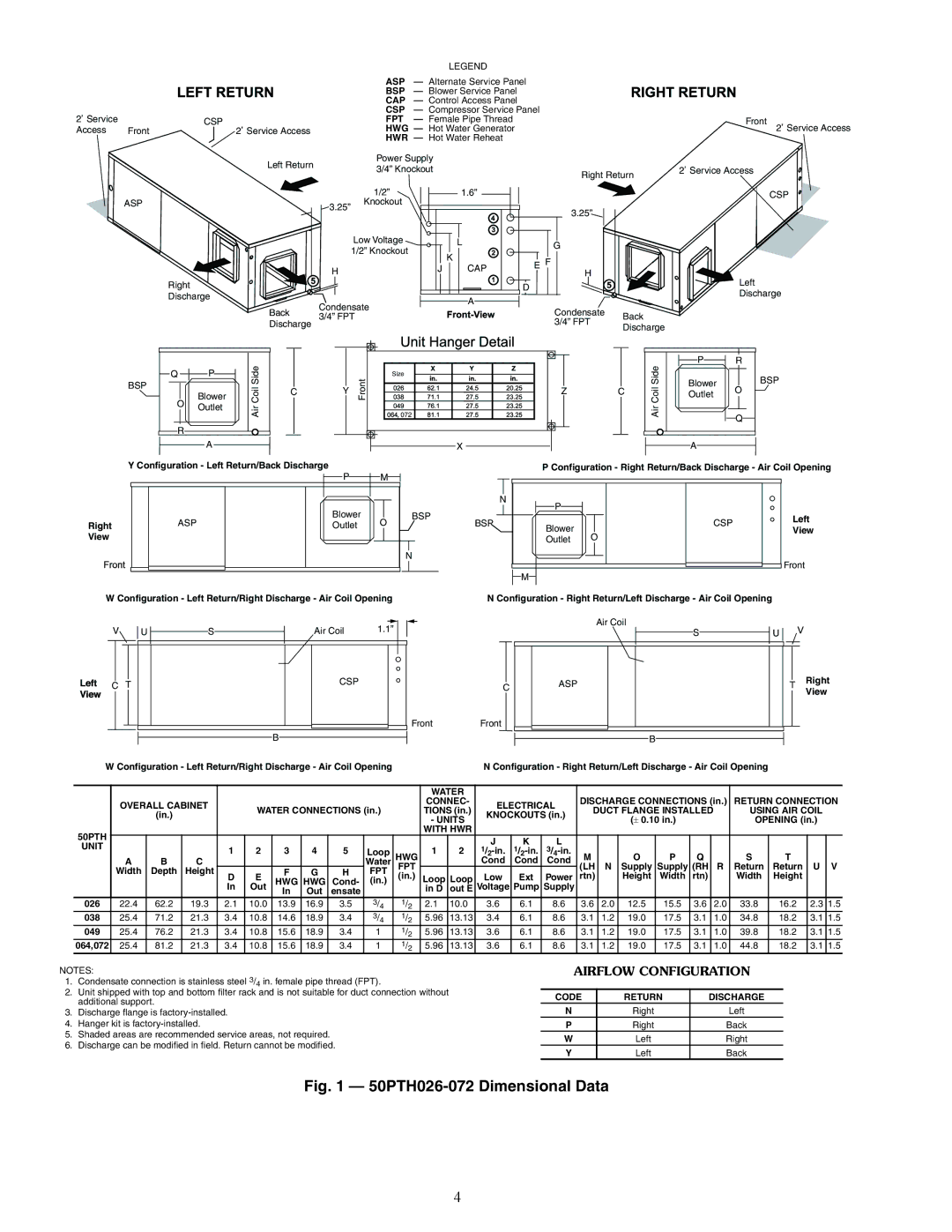
| LEGEND |
|
|
| ASP | — Alternate Service Panel |
|
|
| BSP | — Blower Service Panel |
|
|
| CAP | — Control Access Panel |
|
|
| CSP | — Compressor Service Panel |
2 Service |
| CSP | FPT | — Female Pipe Thread |
Access | Front | 2 Service Access | HWG | — Hot Water Generator |
| HWR — Hot Water Reheat |
Left Return | Power Supply |
3/4” Knockout | |
| Right Return |
Front
2![]() Service Access
Service Access
2![]() Service Access
Service Access
ASP
![]()
![]() 3.25”
3.25”
1/2” Knockout
1.6”
3.25”![]()
![]()
CSP
Right
Discharge
Back
Discharge
Low Voltage
1/2” Knockout
H
Condensate 3/4” FPT
| L |
| G |
|
|
|
|
| |
| K | E | F |
|
J | CAP |
| ||
| H |
| ||
|
|
|
| |
|
| D |
|
|
| A |
|
|
|
|
|
| Condensate | Back |
|
|
| 3/4” FPT | |
|
|
| Discharge | |
|
|
|
|
![]() Left Discharge
Left Discharge
|
|
| ide |
|
|
|
|
|
| ide | P | R |
Q |
| P |
|
| Size |
|
|
|
| BSP | ||
BSP |
|
| CoilS |
| Front |
|
|
|
| CoilS | Blower | |
|
| C | Y |
|
|
| Z | C |
| O | ||
|
| Blower |
|
|
|
| Outlet | |||||
O |
|
|
|
|
|
|
|
|
| |||
Outlet | Air |
|
|
|
|
|
| Air |
|
| ||
|
|
|
| , 072 |
|
|
|
|
| |||
|
|
|
|
|
|
|
|
| Q | |||
|
|
|
|
|
|
|
|
|
|
|
| |
R |
|
|
|
|
|
|
|
|
|
|
| |
|
| A |
|
|
|
| X |
|
|
| A |
|
Y Configuration - Left Return/Back Discharge | P |
| M |
| P Configuration - Right Return/Back Discharge - Air Coil Opening | |||||||
|
|
|
|
|
|
|
|
|
|
| ||
|
|
|
|
|
|
|
| N |
|
|
|
|
|
|
|
| Blower |
| BSP | P |
|
|
|
| |
| ASP |
|
| O |
|
|
| CSP | Left | |||
Right |
|
| Outlet |
| BSP | Blower |
|
| ||||
|
|
|
|
| View | |||||||
View |
|
|
|
|
|
|
| O |
|
| ||
|
|
|
|
|
|
| Outlet |
|
|
| ||
|
|
|
|
|
| N |
|
|
|
| Front | |
|
|
|
|
|
|
|
|
|
|
|
| |
|
|
|
|
|
|
|
| M |
|
|
|
|
W Configuration - Left Return/Right Discharge - Air Coil Opening | N Configuration - Right Return/Left Discharge - Air Coil Opening | |||||||||||
|
|
|
|
|
|
|
|
|
|
|
|
|
|
|
|
|
|
|
V |
|
|
|
| U |
|
|
| Air Coil | 1.1” |
| |||||||
|
|
|
|
| S |
|
| |||||||||||
|
|
|
|
|
|
|
|
|
|
|
|
|
|
|
|
|
|
|
|
|
|
|
|
|
|
|
|
|
|
|
|
|
|
|
|
|
|
| C |
|
| T |
|
|
|
|
|
| CSP |
|
|
|
|
| ||
|
|
|
|
|
|
|
|
|
|
|
|
|
|
| ||||
|
|
|
|
|
|
|
|
|
|
|
|
|
|
|
|
|
|
|
Front
B
W Configuration - Left Return/Right Discharge - Air Coil Opening
| Air Coil |
|
|
| S |
|
|
C | ASP | T | Right |
|
| View | |
|
|
| |
Front |
|
|
|
| B |
|
|
N Configuration - Right Return/Left Discharge - Air Coil Opening |
|
| |
|
|
|
|
|
|
|
|
|
|
| WATER |
|
|
|
|
|
|
|
|
|
|
|
|
|
| |
| OVERALL CABINET |
|
|
|
|
|
|
| CONNEC- | ELECTRICAL | DISCHARGE CONNECTIONS (in.) | RETURN CONNECTION | ||||||||||||||
|
| WATER CONNECTIONS (in.) |
| TIONS (in.) | DUCT FLANGE INSTALLED |
| USING AIR COIL | |||||||||||||||||||
|
| (in.) |
|
|
| KNOCKOUTS (in.) |
| |||||||||||||||||||
|
|
|
|
|
|
|
|
|
| - UNITS |
|
| (± 0.10 in.) |
|
|
| OPENING (in.) | |||||||||
|
|
|
|
|
|
|
|
|
|
|
|
|
|
|
|
|
|
| ||||||||
50PTH |
|
|
|
|
|
|
|
|
|
| WITH HWR |
|
|
|
|
|
|
|
|
|
|
|
|
|
| |
UNIT |
|
|
|
|
|
|
|
|
|
|
|
| J | K | L |
|
|
|
|
|
|
|
|
|
|
|
|
|
| 1 | 2 | 3 | 4 | 5 | Loop |
| 1 | 2 |
|
|
|
|
|
|
|
|
|
|
| ||||
|
|
|
| HWG | M |
| O | P | Q |
|
| S | T |
|
| |||||||||||
| A | B | C |
|
|
|
|
| Water | FPT |
|
| Cond | Cond | Cond | (LH | N | Supply | Supply | (RH |
| R | Return | Return | U | V |
| Width | Depth | Height |
|
| F | G | H | FPT |
|
|
|
|
|
| |||||||||||
| D | E | (in.) | Loop | Loop | Low | Ext | Power | rtn) |
| Height | Width | rtn) |
|
| Width | Height |
|
| |||||||
|
|
|
| HWG | HWG | Cond- | (in.) |
|
|
|
|
| ||||||||||||||
|
|
|
| In | Out | In | Out | ensate |
|
| in D | out E | Voltage | Pump | Supply |
|
|
|
|
|
|
|
|
|
|
|
026 | 22.4 | 62.2 | 19.3 | 2.1 | 10.0 | 13.9 | 16.9 | 3.5 | 3/4 | 1/2 | 2.1 | 10.0 | 3.6 | 6.1 | 8.6 | 3.6 | 2.0 | 12.5 | 15.5 | 3.6 |
| 2.0 | 33.8 | 16.2 | 2.3 | 1.5 |
038 | 25.4 | 71.2 | 21.3 | 3.4 | 10.8 | 14.6 | 18.9 | 3.4 | 3/4 | 1/2 | 5.96 | 13.13 | 3.4 | 6.1 | 8.6 | 3.1 | 1.2 | 19.0 | 17.5 | 3.1 |
| 1.0 | 34.8 | 18.2 | 3.1 | 1.5 |
049 | 25.4 | 76.2 | 21.3 | 3.4 | 10.8 | 15.6 | 18.9 | 3.4 | 1 | 1/2 | 5.96 | 13.13 | 3.6 | 6.1 | 8.6 | 3.1 | 1.2 | 19.0 | 17.5 | 3.1 |
| 1.0 | 39.8 | 18.2 | 3.1 | 1.5 |
064,072 | 25.4 | 81.2 | 21.3 | 3.4 | 10.8 | 15.6 | 18.9 | 3.4 | 1 | 1/2 | 5.96 | 13.13 | 3.6 | 6.1 | 8.6 | 3.1 | 1.2 | 19.0 | 17.5 | 3.1 |
| 1.0 | 44.8 | 18.2 | 3.1 | 1.5 |
NOTES:
1.Condensate connection is stainless steel 3/4 in. female pipe thread (FPT).
2.Unit shipped with top and bottom filter rack and is not suitable for duct connection without additional support.
3.Discharge flange is
4.Hanger kit is
5.Shaded areas are recommended service areas, not required.
6.Discharge can be modified in field. Return cannot be modified.
AIRFLOW CONFIGURATION
CODE | RETURN | DISCHARGE |
N | Right | Left |
P | Right | Back |
W | Left | Right |
Y | Left | Back |
Fig. 1 — 50PTH026-072 Dimensional Data
4