| 90.0 | |
| 80.0 | |
| 70.0 | |
(kOhm) | 60.0 | |
50.0 | ||
Resistance | ||
40.0 | ||
|
30.0
20.0
10.0
0.0
0.020.0 40.0 60.0 80.0 100.0 120.0 140.0 Temperature (degF)
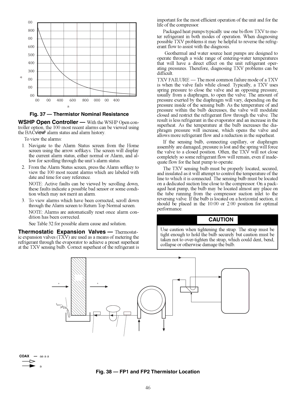
Fig. 37 — Thermistor Nominal Resistance
WSHP Open Controller — With the WSHP Open con- troller option, the 100 most recent alarms can be viewed using the BACview6 alarm status and alarm history.
To view the alarms:
1.Navigate to the Alarm Status screen from the Home screen using the arrow softkeys. The screen will display the current alarm status, either normal or Alarm, and al- low for scrolling through the unit’s alarm status.
2.From the Alarm Status screen, press the Alarm softkey to view the 100 most recent alarms which are labeled with date and time for easy reference.
NOTE: Active faults can be viewed by scrolling down, these faults indicate a possible bad sensor or some condi- tion which may not merit an alarm.
3.To view alarms which have been corrected, scroll down through the Alarm screen to Return Top Normal screen.
NOTE: Alarms are automatically reset once alarm con- dition has been corrected.
See Table 32 for possible alarm cause and solution.
Thermostatic Expansion Valves — Thermostat- ic expansion valves (TXV) are used as a means of metering the refrigerant through the evaporator to achieve a preset superheat at the TXV sensing bulb. Correct superheat of the refrigerant is
important for the most efficient operation of the unit and for the life of the compressor.
Packaged heat pumps typically use one
Geothermal and water source heat pumps are designed to operate through a wide range of
TXV FAILURE — The most common failure mode of a TXV is when the valve fails while closed. Typically, a TXV uses spring pressure to close the valve and an opposing pressure, usually from a diaphragm, to open the valve. The amount of pressure exerted by the diaphragm will vary, depending on the pressure inside of the sensing bulb. As the temperature of and pressure within the bulb decreases, the valve will modulate closed and restrict the refrigerant flow through the valve. The result is less refrigerant in the evaporator and an increase in the superheat. As the temperature at the bulb increases the dia- phragm pressure will increase, which opens the valve and allows more refrigerant flow and a reduction in the superheat.
If the sensing bulb, connecting capillary, or diaphragm assembly are damaged, pressure is lost and the spring will force the valve to a closed position. Often, the TXV will not close completely so some refrigerant flow will remain, even if inade- quate flow for the heat pump to operate.
The TXV sensing bulb must be properly located, secured, and insulated as it will attempt to control the temperature of the line to which it is connected. The sensing bulb must be located on a dedicated suction line close to the compressor. On a pack- aged heat pump, the bulb may be located almost any place on the tube running from the compressor suction inlet to the reversing valve. If the bulb is located on a horizontal section, it should be placed in the 10:00 or 2:00 position for optimal performance.
![]() CAUTION
CAUTION
Use caution when tightening the strap. The strap must be tight enough to hold the bulb securely but caution must be taken not to
AIRFLOW
(°F)
THERMISTOR
AIR |
COIL |
AIRFLOW
(°F)
EXPANSION
VALVE
FP2FP1
COAX
![]() SUCTION
SUCTION
COMPRESSOR
DISCHARGE
CONDENSATE |
|
|
|
|
| |
|
|
|
|
| ||
OVERFLOW | LIQUID |
|
|
|
| |
(CO) |
|
|
|
| ||
LINE | WATER IN | WATER OUT | ||||
| ||||||
AIR COIL |
| |||||
WATER |
|
|
|
| ||
FREEZE |
|
|
|
| ||
PROTECTION | COIL |
|
|
|
| |
| PROTECTION |
|
| |||
LEGEND
COAX — Coaxial Heat Exchanger
Airflow
Refrigerant Liquid Line Flow
Fig. 38 — FP1 and FP2 Thermistor Location
46