Safety Considerations
Contents
General
Installation
Physical Data 50PTH, PTV, PTD026-072 Units
50PTH026-072 Dimensional Data
Aux Electric Heat Disconnect
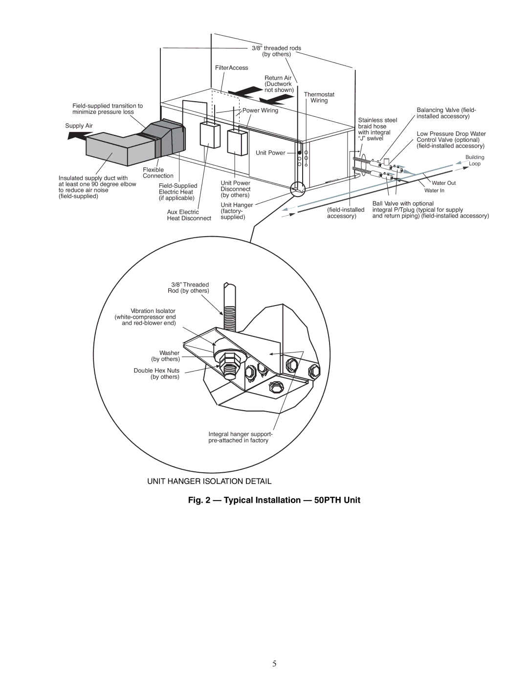
Typical Installation 50PTH Unit
50PTV Dimensional Data
50PTD Dimensional Data
Back Discharge
Side Discharge
Mount the Unit
Install Condensate Drain
Rotate
Move to Side
Trap Condensate Drain
Horizontal Unit Pitch
Drains field-installed
Typical Ground-Water Piping Installation
Metal Hose Minimum Bend Radii
Wire Field Power Supply
Water Quality Guidelines
50PTH,PTV,PTD Electrical Data
Sensor, Water Coil Freeze Protection
Alarm Relay Contacts
Trans
RVS
ECM
BM ECM
Alarm Relay Contacts
Discharge Temp Switch Relay/Contactor Coil
A50-8363
8364
A50
SPT
LWT
Wshp Open Control
A50-8571
SPT Sensors
Rnet Wiring Specifications
Field-Supplied Sensors for Wshp Open Controller
Rnet Wiring
Wire Field Controls
Wire Terminal
A50-8443
A50-7764tf
A50-8141
A50-8441
A50-8442
Dehumidificaton Mode Settings
Cooling Settings
Heating Settings
CFM Adjust Settings
Blower Performance Data
Wshp Open High Fan Airflow
PRE-START-UP
Wshp Open Fan Only / Low Fan and Med Fan Airflow
Field Selectable Inputs
Complete C Control Jumper Settings
Deluxe D Control Jumper Settings
DIP Switch Block S2 Accessory 2 Relay Options
DIP Switch Block S2 Accessory 1 Relay Options
Humidistat/Dehumidistat Logic Deluxe D DIP Switch Settings
Units with Modulating Hot Water Reheat HWR Option
HWR Operating Modes
Mode Input Output
Operating Limits
START-UP
A50-8145 Water Out
Operating Limits 50PTH, PTV, PTD Units
Water Temperature Change Through Heat Exchanger
Unit Start-Up Cooling Mode
Unit Start-Up Heating Mode
Suction Discharge Super Sub Water Air Temp
A50-8444
Unit Start-Up with Wshp Open Controls
Coaxial Water Pressure Drop
Unit 50PTH, PTV Water Temperature F GPM
PTD
026 038 049
Antifreeze Percentages by Volume
Approximate Fluid Volume gal Per 100 Ft of Pipe
Operation
Units with Aquazone Complete C Control
Units with Wshp Open Multiple Protocol
Page
Page
LED Status Description of Operation Alarm Relay
Complete C Control LED Code Fault Descriptions
LED Fault Description Code
Complete C and Deluxe D Board System Test
Aquazone Deluxe D Control LED Indica
Alarm Relay
Service
Refrigerant Charging
Troubleshooting
Air Coil Fan Motor Removal
Replacing the Wshp Open Controller’s Bat
80.0
90.0
70.0
KOhm 60.0 50.0
Page
Fault Description Solution
ECM Troubleshooting
A50-8448
ECM Pin Connectors
A50-8447
ECM Troubleshooting Flow Diagram
Good Practices
Wshp Troubleshooting
Fault Heating Cooling Possible Cause Solution
No Fault Code Shown
Code 7 Auto Resetting
Over/Under Voltage
Performance Monitor
High Head Pressure
Temperature in Heating
Low Suction Pressure
Low Discharge Air
Alarm Status
Appendix a Wshp Open Screen Configuration
Status
Sensor
Maintenance
Appendix a Wshp Open Screen Configuration
System Settings
Configuration
Schedule
Test
Appendix a Wshp Screen Open Configuration
Service
Screen Name
Configuration Service
Point Name Password Editable Range Default Level
Alarm
Page
Page
Copyright 2010 Carrier Corporation
II. START-UP
50PTH,PTV,PTD START-UP Checklist
Cooling Cycle Analysis
Heating Cycle Analysis
A50-8449
A50-8450