|
|
|
|
|
|
|
|
|
|
|
|
|
| + 24vac |
|
|
|
|
|
|
|
|
|
|
|
|
|
| - Gnd |
|
|
|
|
|
|
|
|
|
|
|
| Fan |
| |
FIELD INSTALLED (OPTIONAL) – SEE NOTE 2 |
|
|
|
| Aux Heat |
| ||||||||
|
|
|
|
|
|
|
|
|
|
|
| Reversing Valve | NC FIRE/SMOKE | |
| SPACE RH | PRIMARY | SPACE CO2 |
| PRIMARY | Comp #2 | DETECTOR CONTACT | |||||||
| SENSOR |
|
|
|
| SENSOR |
|
|
| |||||
|
|
|
|
|
|
|
|
|
| Comp #1 |
| |||
| +24vac |
|
|
|
| +24vac |
|
|
|
|
|
| Comp Status | |
|
|
|
|
|
|
|
|
|
|
| ||||
| + |
|
|
|
| + |
|
|
|
|
|
| ||
|
|
|
|
|
|
|
|
|
|
| LWT (Input 6) |
| ||
|
|
|
|
|
|
|
|
|
|
|
| |||
| - |
|
|
|
| - |
|
|
|
|
|
|
|
|
SAT (LAT) (Input 7)
AO1 – Aux Reheat or Cond.
WTR. Loop Econ. (AO 1)
|
|
|
|
| J1 |
| J2 |
|
|
|
|
|
| 1 | 10 | 1 | 7 |
6 | 5 | 4 | 3 | 2 |
| CONDENSATE | ||
1 |
|
| ||||||
|
|
|
|
|
|
|
| OVERFLOW SWITCH |
J4
8 | 7 | 6 | 5 | 4 | 3 | 2 | 1 |
J5
REMOTE OCCUPANCY/
FAN STATUS SWITCH
OA DAMPER
|
|
|
|
| LEGEND | ||||
AI |
|
| — |
| Analog Input | ||||
AO |
|
| — |
| Analog Output | ||||
BI |
|
| — |
| Binary Input | ||||
BO |
|
| — |
| Binary Output | ||||
SPT |
|
| — |
| Space Temperature | ||||
|
|
|
|
|
|
|
|
| Factory Wiring |
|
|
|
|
|
|
|
|
| Field Wiring |
|
|
|
|
|
|
|
|
| |
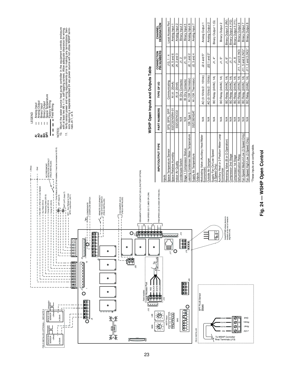
NOTES:
10.Mount the water source heat pump controller in the equipment controls enclosure with at least two #6 x 1 in.
11.Verify sensor power and wiring requirements prior to making any terminations. Sen- sors requiring a separate isolated 24 vac power source will not utilize WSHP termi- nals
a50-8571
23
|
|
|
|
|
|
|
|
|
|
|
|
|
|
|
| 2 |
|
|
|
|
|
|
|
|
|
|
|
|
|
|
|
|
|
|
|
|
|
|
|
|
|
| 1 |
|
|
|
|
|
|
|
|
|
|
|
|
|
|
|
|
|
|
|
|
|
|
|
|
|
| J22 |
|
| J11 |
|
|
|
|
|
|
|
|
|
|
|
|
|
|
|
|
|
|
|
|
|
|
|
|
|
|
|
|
|
|
|
|
| |
|
|
|
|
|
|
|
|
|
|
|
|
|
|
|
|
|
|
| 8 | DEHUMIDIFY OUTPUT CONTACT |
|
|
|
|
| |
|
|
|
|
|
|
|
|
|
|
|
|
|
|
|
|
|
|
|
|
|
|
|
|
| ||
|
|
|
|
|
|
|
|
|
|
|
| Field Installed |
|
|
|
|
| 7 |
|
|
|
|
|
|
| |
|
|
|
|
|
|
|
|
|
|
|
|
|
|
|
|
| 6 |
|
|
|
|
|
|
| ||
|
|
|
|
|
|
|
|
|
|
|
| Local Access Port |
|
|
|
|
|
|
|
|
|
| ||||
|
|
|
|
|
|
|
|
|
|
| J12 |
|
|
| 4 5 | FAN SPEED |
| WSHP Open Inputs and Outputs Table |
| |||||||
|
|
|
|
|
|
|
|
|
|
|
|
|
|
|
|
|
|
|
| |||||||
|
| MSB |
|
| LSB |
|
| 4 | RED |
|
|
|
|
|
|
| ||||||||||
|
|
|
|
|
| 3 | BLACK |
| To |
|
|
|
|
|
|
|
|
|
| |||||||
|
|
| 0 |
|
|
|
| 0 |
|
|
|
|
|
| 3 |
|
|
|
|
|
|
| ||||
|
| 9 | 1 |
|
| 9 | 1 |
|
| 2 | WHITE |
| SPT PLUS |
|
| 2 |
|
|
|
|
| CONNECTION | CHANNEL | |||
|
|
|
| 2 |
|
|
|
|
|
|
|
|
| INPUT/OUTPUT TYPE |
| PART NUMBERS | TYPE OF I/O | |||||||||
| 8 |
|
|
| 8 |
|
|
| 2 |
|
|
|
| FAN SPEED |
| |||||||||||
| 7 |
|
|
| 3 | 7 |
|
|
| 3 |
| 1 | GREEN |
|
|
|
| 1 |
| PIN NUMBERS | DESIGNATION | |||||
|
|
| 4 |
|
| 4 |
|
|
|
|
|
|
|
|
|
| ||||||||||
| 6 |
| 5 |
| 6 |
| 5 |
|
|
|
|
|
|
|
|
|
|
| Inputs |
|
|
|
|
| ||
|
|
|
|
|
|
|
|
|
| J13 |
|
|
|
|
|
|
|
|
|
|
|
|
| |||
|
|
|
| MSTP Baud |
|
|
|
|
|
|
|
|
|
|
|
|
|
|
|
| ||||||
|
|
|
|
|
|
|
|
|
|
|
|
|
|
|
| Space Temperature Sensor |
| SPS, SPPL, SPP | Communicating | J13, 1 - 4 | Local Access Port | |||||
|
|
| 9600 | 19.2k | 38.4k | 76.8k |
|
|
|
|
|
| J17 |
|
|
|
|
| ||||||||
|
|
|
|
|
|
|
|
|
|
|
|
|
|
|
|
|
|
| ||||||||
|
|
|
|
|
|
|
|
|
|
|
|
|
|
|
|
|
|
|
| Space Relative Humidity |
| AI (4 - 20mA) | J4, 5 and 6 | Analog Input 1 | ||
|
|
|
|
|
|
|
|
|
|
|
|
|
|
|
|
|
|
|
|
|
| |||||
|
|
|
|
| SW3 |
|
|
|
|
|
|
|
|
|
|
|
|
|
| Indoor Air Quality |
| 33ZCSENCO2 | AI (4 | J4, 2 and 3 | Analog Input 2 | |
|
|
|
|
|
|
|
|
|
|
|
|
|
|
|
| 1 | 2 | 3 | J14 |
| Condensate Switch |
| N/A | BI (Dry Contacts) | J1, 2 | Binary Input 3 |
|
|
|
|
|
|
|
|
|
|
| N | 4 | 3 | 2 | 1 | J19 |
|
|
|
| Stage 1 Compressor Status |
| N/A | BI (Dry Contacts) | J1, 10 | Binary Input 5 |
| 8 |
| 7 | 6 | 5 | 4 | 3 |
| 2 | 1 | O |
|
|
|
| Leaving Condenser Water Temperature |
| 10K Type II | AI (10K Thermistor) | J2, 1 and 2 | Analog Input 6 | |||||
|
|
|
| J20 |
|
|
|
|
| |||||||||||||||||
|
|
|
|
|
|
|
|
|
|
|
|
|
|
|
|
|
|
|
|
| ||||||
|
|
|
|
|
|
|
|
|
|
|
|
|
|
|
|
|
|
|
|
| Supply Air Temperature |
| 33ZCSENSAT | AI (10K Thermistor) | J2, 3 and 4 | Analog Input 7 |
FIELD INSTALLED |
|
|
|
|
|
|
|
|
|
|
|
|
|
|
|
|
|
| Outputs |
|
|
|
|
| ||
|
|
|
|
|
|
|
|
|
|
| SPT PLUS Sensor |
|
|
|
|
|
|
|
|
|
|
|
|
| ||
|
|
|
|
|
|
|
|
|
|
|
|
|
|
|
|
|
|
| Modulating Valve (Auxiliary Heat/Water |
|
|
|
|
| ||
|
|
|
|
|
|
|
|
|
|
| Shown |
|
|
|
|
|
|
|
|
|
| N/A | AO | J2 4 and 5* | Analog Output 1 | |
|
|
|
|
|
|
|
|
|
|
|
|
|
|
|
|
|
|
|
|
| Economizer) |
| ||||
|
|
|
|
|
|
|
|
|
|
|
|
|
|
|
|
|
|
|
|
|
|
|
|
|
| |
|
|
|
|
|
|
|
|
|
|
|
|
|
|
|
|
|
|
|
|
| Outside Air Damper |
| N/A | AO | J22 1 and 2* | Analog Output 2 |
|
|
|
|
|
|
|
|
|
|
|
|
|
|
|
|
|
|
|
|
| Supply Fan On/Low Speed |
| N/A | BO Relay (24VAC, 1A) | J1, 4* | Binary Output 1 (G) |
To WSHPController RnetTerminals(J13) |
|
|
|
|
|
|
|
|
|
|
|
|
|
|
|
|
| LED1 |
|
| (3 Speed Only) |
| ||||
|
|
|
|
|
|
|
|
|
|
|
|
|
|
|
|
| DB |
|
|
|
|
|
| |||
|
|
|
|
|
|
|
|
|
|
|
|
|
|
|
|
|
|
| Auxiliary Heat or |
|
|
|
|
| ||
|
| BLACK |
| WHITE | GREEN |
|
|
|
|
|
|
|
|
|
|
|
|
|
|
| N/A | BO Relay (24VAC, 1A) | J1, 5* | Binary Output 2 | ||
RED |
|
|
|
|
|
|
|
|
|
|
|
|
|
|
|
| Economizer |
| ||||||||
|
|
|
|
|
|
|
|
|
|
|
|
|
|
|
|
|
|
|
|
| ||||||
|
|
|
|
|
|
|
|
|
|
|
|
|
|
|
|
|
|
|
|
|
|
|
|
|
| |
|
|
|
|
|
|
|
|
|
|
|
|
|
|
|
|
|
| Install BT485 where device is | Reversing Valve (B or O Operation) |
| N/A | BO Relay (24VAC, 1A) | J1, 6* | Binary Output 3 (RV) | ||
|
|
|
|
|
|
|
|
|
|
|
|
|
|
|
|
|
| located at the end of network |
| |||||||
|
|
|
|
|
|
|
|
|
|
|
|
|
|
|
|
|
| segment only. |
| Compressor 2nd Stage |
| N/A | BO Relay (24VAC, 1A) | J1, 7 | Binary Output 4 (Y2) | |
|
|
|
|
|
|
|
|
|
|
|
|
|
|
|
|
|
|
|
|
|
| |||||
|
|
|
|
|
|
|
|
|
|
|
|
|
|
|
|
|
|
|
|
| Compressor 1st Stage |
| N/A | BO Relay (24VAC, 1A) | J1, 8 | Binary Output 5 (Y1) |
|
|
|
|
|
|
|
|
|
|
|
|
|
|
|
|
|
|
|
|
| Dehumidification Relay |
| N/A | BO Relay (24VAC, 1A) | J11, 7 and 8 (NO) | Binary Output 6 |
| +12V |
| Rnet- |
| Rnet+ | Gnd |
|
|
|
|
|
|
|
|
|
|
|
|
| Fan Speed Medium/Low (3 Speed Only) | N/A | BO Relay (24VAC, 1A) | J11, 5 and 6 (NO)* | Binary Output 7 | ||
|
|
|
|
|
|
|
|
|
|
|
|
|
|
|
| Fan Speed High/Low (3 Speed Only) |
| N/A | BO Relay (24VAC, 1A) | J11, 2 and 3 (NO)* | Binary Output 8 | |||||
|
|
|
|
|
|
|
|
|
|
|
|
|
|
|
|
|
|
|
|
| *These inputs are configurable. |
|
|
|
|
|