Step 10 — Operate ECM Interface Board
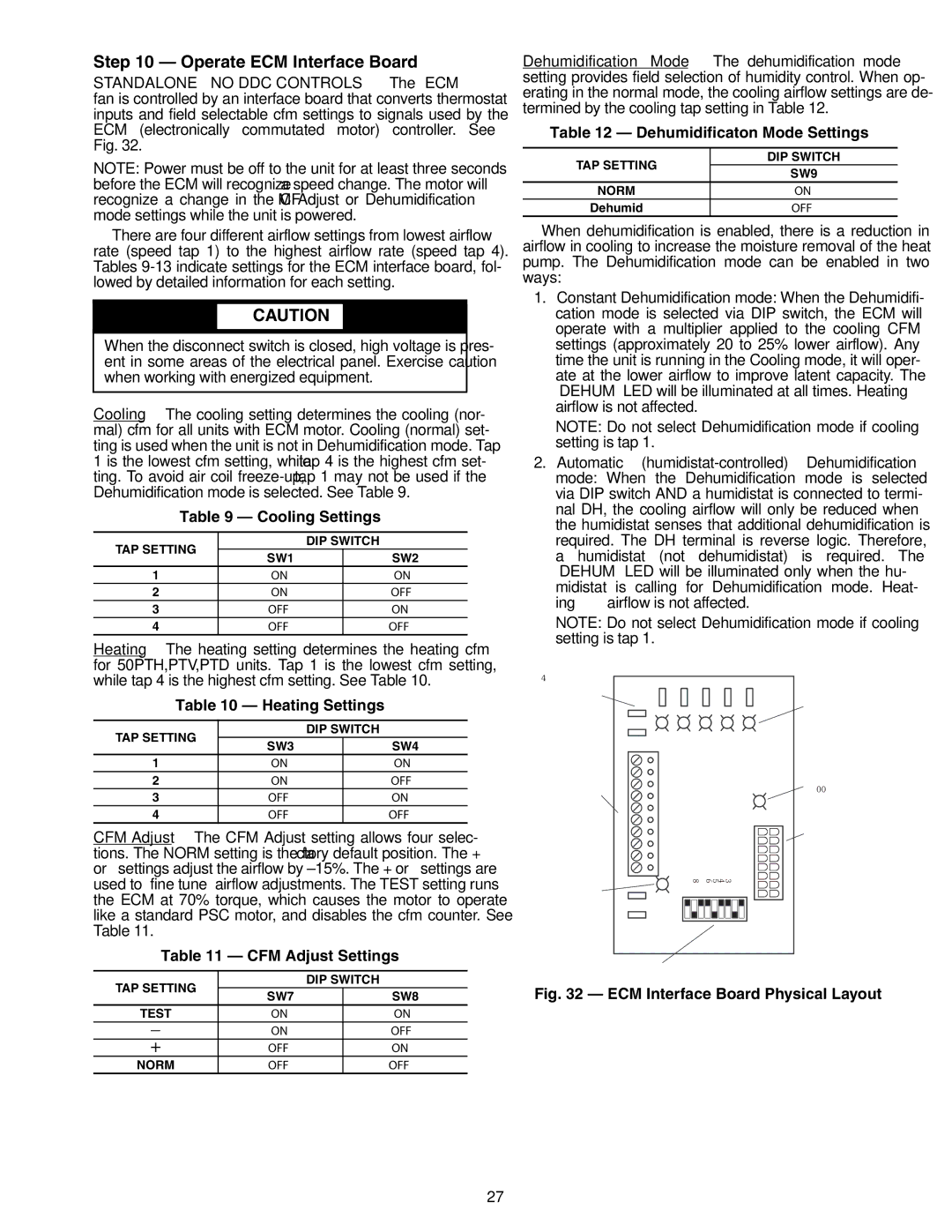
STANDALONE — NO DDC CONTROLS — The ECM fan is controlled by an interface board that converts thermostat inputs and field selectable cfm settings to signals used by the ECM (electronically commutated motor) controller. See Fig. 32.
NOTE: Power must be off to the unit for at least three seconds before the ECM will recognize a speed change. The motor will recognize a change in the CFM Adjust or Dehumidification mode settings while the unit is powered.
There are four different airflow settings from lowest airflow rate (speed tap 1) to the highest airflow rate (speed tap 4). Tables
![]() CAUTION
CAUTION
When the disconnect switch is closed, high voltage is pres- ent in some areas of the electrical panel. Exercise caution when working with energized equipment.
Cooling — The cooling setting determines the cooling (nor- mal) cfm for all units with ECM motor. Cooling (normal) set- ting is used when the unit is not in Dehumidification mode. Tap 1 is the lowest cfm setting, while tap 4 is the highest cfm set- ting. To avoid air coil
| Table 9 — Cooling Settings |
| ||
TAP SETTING | DIP SWITCH |
| ||
SW1 |
| SW2 | ||
|
|
| ||
1 |
| ON |
| ON |
2 |
| ON |
| OFF |
3 |
| OFF |
| ON |
4 |
| OFF |
| OFF |
Heating — The heating setting determines the heating cfm for 50PTH,PTV,PTD units. Tap 1 is the lowest cfm setting,
Dehumidification Mode — The dehumidification mode setting provides field selection of humidity control. When op- erating in the normal mode, the cooling airflow settings are de- termined by the cooling tap setting in Table 12.
Table 12 — Dehumidificaton Mode Settings
TAP SETTING | DIP SWITCH | |
SW9 | ||
| ||
NORM | ON | |
Dehumid | OFF |
When dehumidification is enabled, there is a reduction in airflow in cooling to increase the moisture removal of the heat pump. The Dehumidification mode can be enabled in two ways:
1.Constant Dehumidification mode: When the Dehumidifi- cation mode is selected via DIP switch, the ECM will operate with a multiplier applied to the cooling CFM settings (approximately 20 to 25% lower airflow). Any time the unit is running in the Cooling mode, it will oper- ate at the lower airflow to improve latent capacity. The “DEHUM” LED will be illuminated at all times. Heating airflow is not affected.
NOTE: Do not select Dehumidification mode if cooling setting is tap 1.
2.Automatic
“DEHUM” LED will be illuminated only when the hu- midistat is calling for Dehumidification mode. Heat-
ing | airflow is not affected. |
NOTE: Do not select Dehumidification mode if cooling setting is tap 1.
while tap 4 is the highest cfm setting. See Table 10.
Table 10 — Heating Settings
TAP SETTING |
| DIP SWITCH | |
SW3 |
| SW4 | |
|
| ||
1 | ON |
| ON |
2 | ON |
| OFF |
3 | OFF |
| ON |
4 | OFF |
| OFF |
CFM Adjust — The CFM Adjust setting allows four selec- tions. The NORM setting is the factory default position. The + or – settings adjust the airflow by ±15%. The + or – settings are used to “fine tune” airflow adjustments. The TEST setting runs the ECM at 70% torque, which causes the motor to operate like a standard PSC motor, and disables the cfm counter. See Table 11.
Table 11 — CFM Adjust Settings
1/4" SPADE
CONNECTIONS
TO COMPLETE C OR DELUXE D BOARD
THERMOSTAT
CONNECTIONS
DEHUMIDIFICATION
LED
TB1 R C Y2 Y1 G O W C R DH AL1 A A AL1![]()
![]()
![]()
![]()
![]()
G | Y1 | Y2 | O | W |
G G G G R
|
|
|
| CFM | Y |
|
|
|
|
| |
G |
| SW2 SW3 SW4 SW5 SW6 SW7 SW8 SW9 | SW1 |
|
|
DEHUM | OFF ON | S1 | J1 |
THERMOSTAT
INPUT LEDS
CFM COUNTER
1 FLASH PER 100 CFM
ECM MOTOR
LOW VOLTAGE
CONNECTOR
TAP SETTING |
| DIP SWITCH | |
SW7 |
| SW8 | |
|
| ||
TEST | ON |
| ON |
– | ON |
| OFF |
+ | OFF |
| ON |
NORM | OFF |
| OFF |
FAN SPEED SELECTION DIP SWITCH
Fig. 32 — ECM Interface Board Physical Layout
27