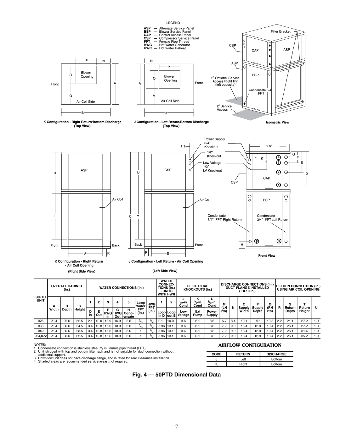
LEGEND
ASP — Alternate Service Panel
BSP — Blower Service Panel
CAP — Control Access Panel
CSP — Compressor Service Panel
FPT — Female Pipe Thread
HWG — Hot Water Generator
HWR — Hot Water Reheat
|
|
|
|
|
|
|
|
|
|
| WATER |
|
|
|
|
|
|
|
|
|
|
|
| |
| OVERALL CABINET |
| WATER CONNECTIONS (in.) |
| CONNEC- | ELECTRICAL | DISCHARGE CONNECTIONS (in.) | RETURN CONNECTION (in.) | ||||||||||||||||
|
| (in.) |
|
|
| TIONS (in.) | KNOCKOUTS (in.) | DUCT FLANGE INSTALLED | USING AIR COIL OPENING | |||||||||||||||
|
|
|
|
|
|
|
|
|
| - UNITS |
|
| (± 0.10 in.) |
| ||||||||||
|
|
|
|
|
|
|
|
|
|
|
|
|
|
|
|
|
|
|
|
| ||||
50PTD |
|
|
|
|
|
|
|
|
|
| WITH HWR |
|
|
|
|
|
|
|
|
|
|
|
| |
UNIT |
|
|
|
|
|
|
|
|
|
|
|
| J | K | L |
|
|
|
|
|
|
|
|
|
|
|
| 1 | 2 | 3 | 4 | 5 | Loop | HWG | 1 | 2 | M |
| O | P | Q |
| S | T |
| ||||
|
|
|
|
|
|
| ||||||||||||||||||
| A | B | C |
|
|
|
|
| Water |
|
| Cond | Cond | Cond |
|
|
| |||||||
| Width | Depth | Height |
|
|
|
|
| FPT | FPT |
|
|
|
|
| (LH | N | Supply | Supply | (RH | R | Return | Return | U |
|
|
| F | G | H |
|
|
|
|
| ||||||||||||||
| D | E | (in.) | Loop | Loop | Low | Ext | Power | rtn) |
| Width | Depth | rtn) |
| Depth | Height |
| |||||||
|
|
|
| HWG | HWG | Cond- | (in.) |
|
|
| ||||||||||||||
|
|
|
| In | Out | In | Out | ensate |
|
| in D | out E | Voltage | Pump | Supply |
|
|
|
|
|
|
|
|
|
026 | 22.4 | 25.6 | 52.5 | 2.1 | 10.0 | 13.9 | 16.9 | 3.6 | 3/4 | 1/2 | 2.1 | 10.0 | 3.6 | 6.1 | 8.6 | 6.7 | 8.4 | 10.1 | 9.1 | 10.8 | 2.2 | 21.1 | 27.2 | 1.0 |
038 | 25.4 | 30.6 | 54.5 | 3.4 | 10.8 | 15.6 | 18.9 | 3.6 | 3/4 | 1/2 | 5.96 | 13.13 | 3.6 | 6.1 | 8.6 | 7.2 | 9.0 | 13.4 | 12.9 | 10.4 | 2.2 | 26.1 | 27.2 | 1.0 |
049 | 25.4 | 30.6 | 58.5 | 3.4 | 10.8 | 15.6 | 18.9 | 3.6 | 1 | 1/2 | 5.96 | 13.13 | 3.6 | 6.1 | 8.6 | 7.2 | 9.0 | 13.4 | 12.9 | 10.4 | 2.2 | 26.1 | 31.4 | 1.0 |
064,072 | 25.4 | 30.6 | 62.5 | 3.4 | 10.8 | 15.6 | 18.9 | 3.6 | 1 | 1/2 | 5.96 | 13.13 | 3.6 | 6.1 | 8.6 | 7.2 | 9.0 | 13.4 | 12.9 | 10.4 | 2.2 | 26.1 | 35.2 | 1.0 |
NOTES:
1.Condensate connection is stainless steel 3/4 in. female pipe thread (FPT).
2.Unit shipped with top and bottom filter rack and is not suitable for duct connection without additional support.
3.Downflow unit does not have discharge flange, and is rated for zero clearance installation.
4.Shaded areas are recommended service areas, not required.
AIRFLOW CONFIGURATION
CODE | RETURN | DISCHARGE |
J | Left | Bottom |
K | Right | Bottom |
Fig. 4 — 50PTD Dimensional Data
7