Conventions | Page iii |
Conventions
Notational
Graphic
This manual incorporates the following conventions:
1.An upper case letter H following a number indicates the number is a hexadecimal value (e.g., 32 = 20H and 255 = FFH).
2.In this document, a byte is defined as an
3.This manual represents all memory ordering in the Motorola format. This means that the least significant byte of a double word is placed in the most significant memory location. For a further discussion of memory ordering and information to use Intel ordering, see Chapter 8.
4.The title of this manual, and all references to the adapter throughout, express the name of the product as Rimfire 3880. This name is a base model number representing a series of product offerings with differences that are noted in the text of this manual when pertinent.
To explain the RF3880 command structures and describe the breakdown of the command structure into fields,
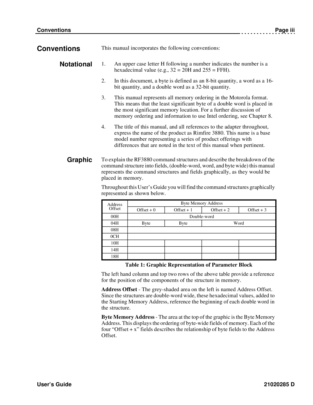
Throughout this User’s Guide you will find the command structures graphically represented as shown below.
Address |
| Byte Memory Address |
|
| |
Offset | Offset + 0 | Offset + 1 | Offset + 2 |
| Offset + 3 |
|
| ||||
00H |
|
|
| ||
|
|
|
|
|
|
04H | Byte | Byte |
| Word | |
|
|
|
|
|
|
08H |
|
|
|
|
|
|
|
|
|
|
|
0CH |
|
|
|
|
|
|
|
|
|
|
|
10H |
|
|
|
|
|
|
|
|
|
|
|
14H |
|
|
|
|
|
|
|
|
|
|
|
18H |
|
|
|
|
|
Table 1: Graphic Representation of Parameter Block
The left hand column and top two rows of the above table provide a reference for the position of the components of the structure in memory.
Address Offset - The
Byte Memory Address - The area at the top of the graphic is the Byte Memory Address. This displays the ordering of
User’s Guide | 21020285 D |
