Chapter 3 Hardware Installation
Page 3 - 12 |
| Step 4: Apply power and observe LEDs |
Step 4: Apply power and observe LEDs
Meaning of
LED’s
After you have inserted the board into the VMEbus slot, apply power to the system.
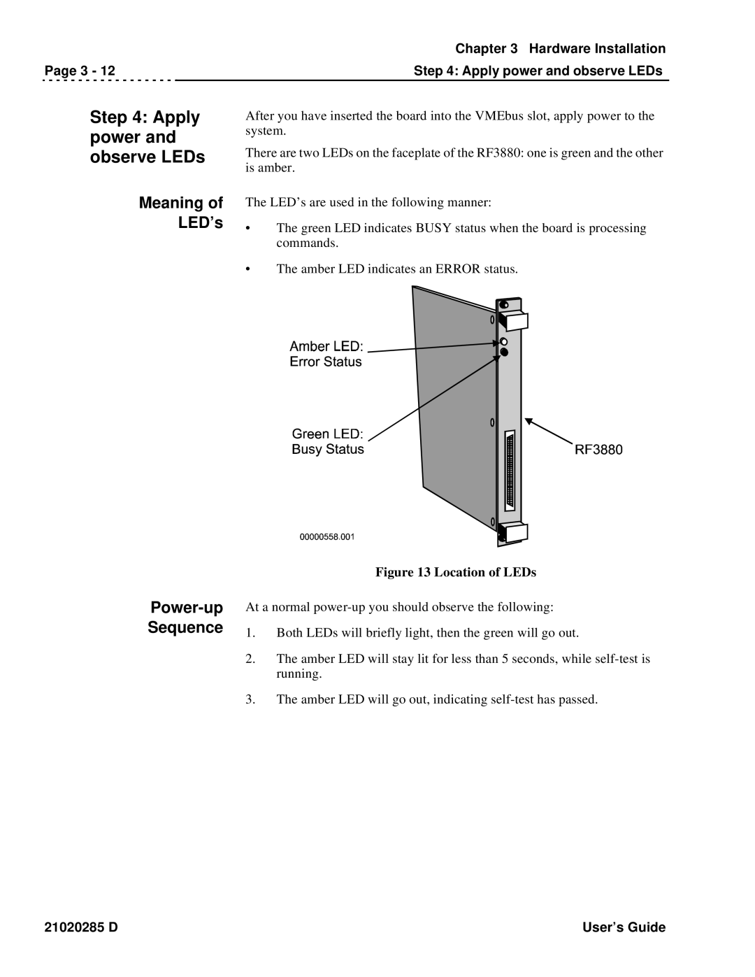
There are two LEDs on the faceplate of the RF3880: one is green and the other is amber.
The LED’s are used in the following manner:
•The green LED indicates BUSY status when the board is processing commands.
•The amber LED indicates an ERROR status.
Power-up Sequence
Figure 13 Location of LEDs
At a normal
1.Both LEDs will briefly light, then the green will go out.
2.The amber LED will stay lit for less than 5 seconds, while
3.The amber LED will go out, indicating
21020285 D | User’s Guide |