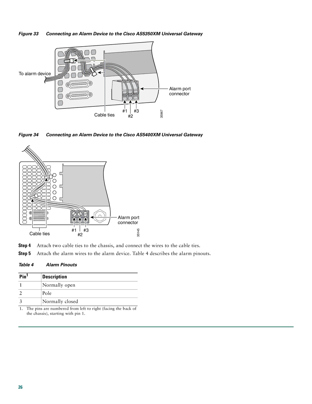
Figure 33 Connecting an Alarm Device to the Cisco AS5350XM Universal Gateway
To alarm device
|
|
|
|
|
#1 |
| #3 | ||
Cable ties | #2 |
| ||
Alarm port connector
35967
Figure 34 Connecting an Alarm Device to the Cisco AS5400XM Universal Gateway
|
|
|
|
|
|
|
|
|
|
|
|
|
|
|
|
|
|
|
|
|
|
|
|
|
|
|
|
|
|
|
|
|
|
|
|
|
|
|
|
|
|
|
|
|
|
|
|
|
|
|
|
|
|
|
|
|
|
|
|
|
|
|
| #1 |
| #3 | |||||
Cable ties | #2 |
| ||||||
Alarm port connector
35145
Step 4 Attach two cable ties to the chassis, and connect the wires to the cable ties. Step 5 Attach the alarm wires to the alarm device. Table 4 describes the alarm pinouts.
Table 4 Alarm Pinouts
Pin1 Description
1Normally open
2Pole
3Normally closed
1.The pins are numbered from left to right (facing the back of the chassis), starting with pin 1.
26