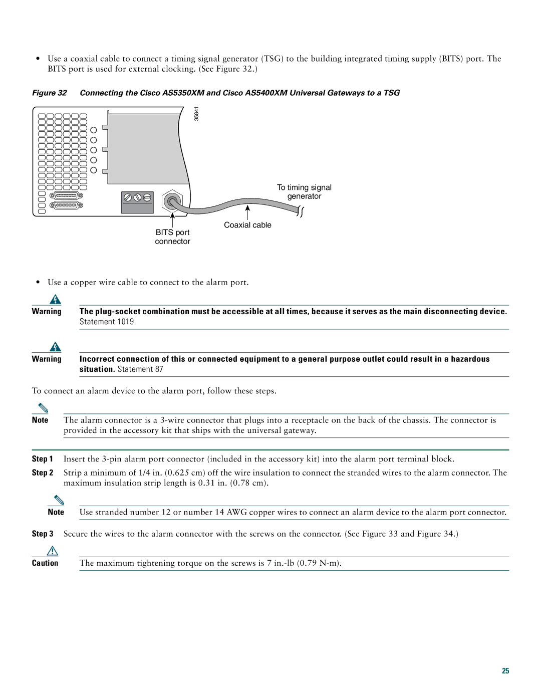
•Use a coaxial cable to connect a timing signal generator (TSG) to the building integrated timing supply (BITS) port. The BITS port is used for external clocking. (See Figure 32.)
Figure 32 Connecting the Cisco AS5350XM and Cisco AS5400XM Universal Gateways to a TSG
35841
To timing signal
generator
![]() Coaxial cable BITS port
Coaxial cable BITS port
connector
•Use a copper wire cable to connect to the alarm port.
Warning | The | |
|
| Statement 1019 |
|
|
|
|
|
|
Warning | Incorrect connection of this or connected equipment to a general purpose outlet could result in a hazardous | |
|
| situation. Statement 87 |
|
|
|
To connect an alarm device to the alarm port, follow these steps.
Note The alarm connector is a
Step 1 Insert the
Step 2 Strip a minimum of 1/4 in. (0.625 cm) off the wire insulation to connect the stranded wires to the alarm connector. The maximum insulation strip length is 0.31 in. (0.78 cm).
Note Use stranded number 12 or number 14 AWG copper wires to connect an alarm device to the alarm port connector.
Step 3 Secure the wires to the alarm connector with the screws on the connector. (See Figure 33 and Figure 34.)
Caution The maximum tightening torque on the screws is 7
25