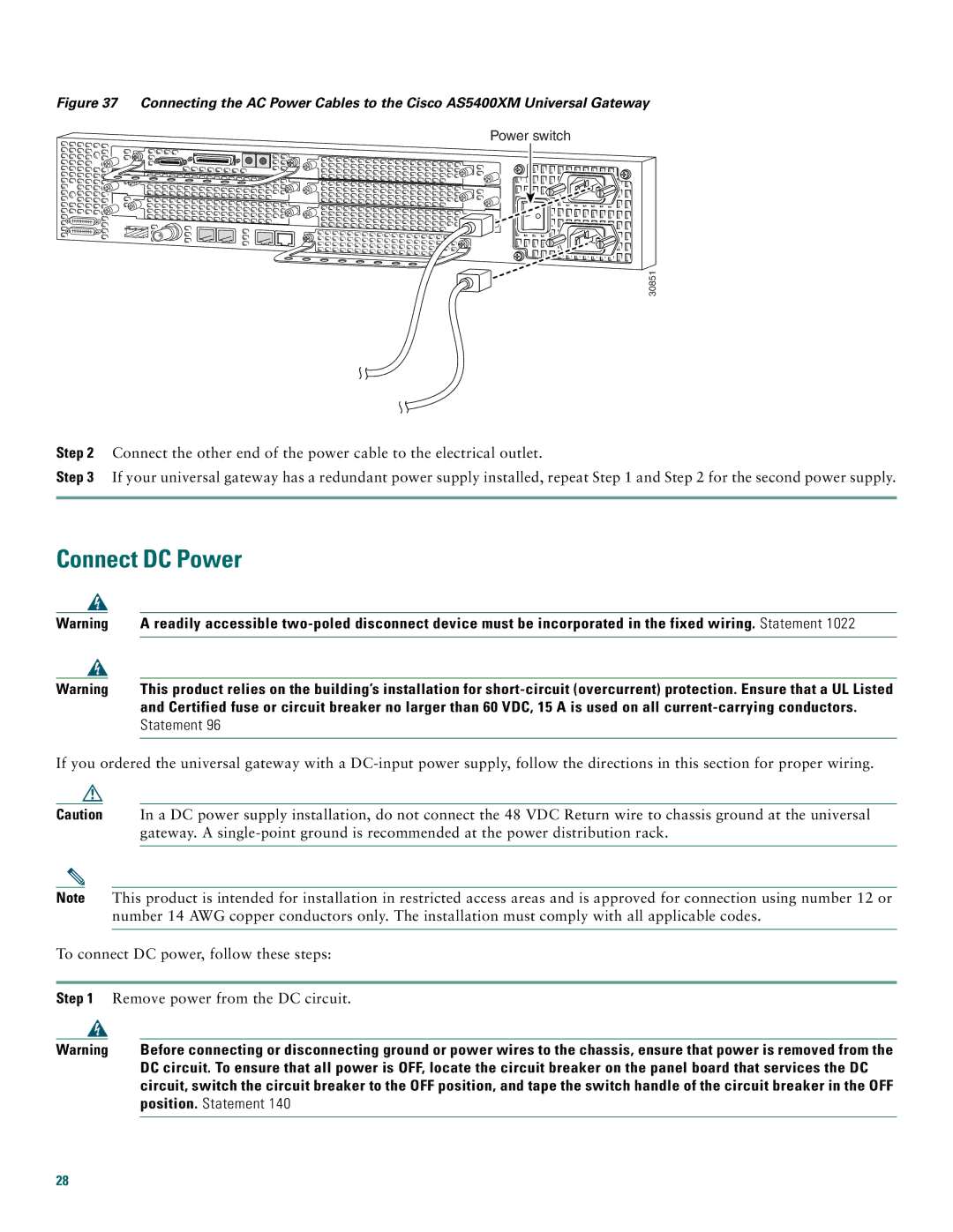
Figure 37 Connecting the AC Power Cables to the Cisco AS5400XM Universal Gateway
Power switch
30851
Step 2 Connect the other end of the power cable to the electrical outlet.
Step 3 If your universal gateway has a redundant power supply installed, repeat Step 1 and Step 2 for the second power supply.
Connect DC Power
Warning | A readily accessible | |
|
|
|
Warning | This product relies on the building’s installation for | |
|
| and Certified fuse or circuit breaker no larger than 60 VDC, 15 A is used on all |
|
| Statement 96 |
|
|
|
If you ordered the universal gateway with a
Caution In a DC power supply installation, do not connect the 48 VDC Return wire to chassis ground at the universal gateway. A
Note This product is intended for installation in restricted access areas and is approved for connection using number 12 or number 14 AWG copper conductors only. The installation must comply with all applicable codes.
To connect DC power, follow these steps:
Step 1 Remove power from the DC circuit.
Warning | Before connecting or disconnecting ground or power wires to the chassis, ensure that power is removed from the |
| DC circuit. To ensure that all power is OFF, locate the circuit breaker on the panel board that services the DC |
| circuit, switch the circuit breaker to the OFF position, and tape the switch handle of the circuit breaker in the OFF |
| position. Statement 140 |
|
|
28