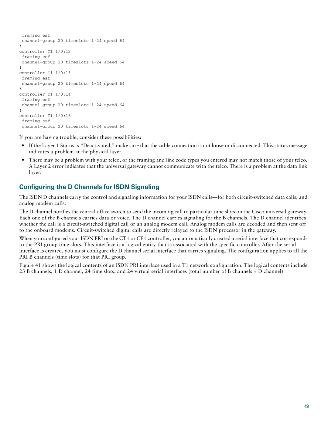
framing esf
!
controller T1 1/0:12 framing esf
!
controller T1 1/0:13 framing esf
!
controller T1 1/0:14 framing esf
!
controller T1 1/0:15 framing esf
If you are having trouble, consider these possibilities:
•If the Layer 1 Status is “Deactivated,” make sure that the cable connection is not loose or disconnected. This status message indicates a problem at the physical layer.
•There may be a problem with your telco, or the framing and line code types you entered may not match those of your telco. A Layer 2 error indicates that the universal gateway cannot communicate with the telco. There is a problem at the data link layer.
Configuring the D Channels for ISDN Signaling
The ISDN D channels carry the control and signaling information for your ISDN
The D channel notifies the central office switch to send the incoming call to particular time slots on the Cisco universal gateway. Each one of the B channels carries data or voice. The D channel carries signaling for the B channels. The D channel identifies whether the call is a
When you configured your ISDN PRI on the CT1 or CE1 controller, you automatically created a serial interface that corresponds to the PRI group time slots. This interface is a logical entity that is associated with the specific controller. After the serial interface is created, you must configure the D channel serial interface that carries signaling. The configuration applies to all the PRI B channels (time slots) for that PRI group.
Figure 41 shows the logical contents of an ISDN PRI interface used in a T1 network configuration. The logical contents include 23 B channels, 1 D channel, 24 time slots, and 24 virtual serial interfaces (total number of B channels + D channel).
49
