Table 1 | LEDs (continued) |
|
| |
|
|
|
| |
Feature Card | LED | State | Description | |
|
|
|
| |
Voice feature | ACTIVITY | Green (blinking) | There is call activity on the feature card. | |
card |
|
|
|
|
|
| Off | There is no activity on the feature card. | |
|
|
| ||
|
|
|
|
|
|
| OK/MAINT | Green | The feature card passed initial |
|
|
|
| is operating normally. |
|
|
|
|
|
|
|
| Yellow | • The feature card is busied out, but there are active calls. |
|
|
|
| Once all the calls are terminated the feature card will be |
|
|
|
| powered off. |
|
|
|
| • The feature card is not functioning correctly. |
|
|
|
|
|
|
|
| Off | All calls associated with the feature card have been shut down, |
|
|
|
| and it is safe to remove the card with the system powered on. |
|
|
|
|
|
1. To display information about an M13 alarm, use the show controllers t3 user EXEC command.
5Connect Cables
Note The information in this document applies to the Cisco AS5350XM and Cisco AS5400XM universal gateways.
System Management and Power Connections
The connections described here provide electrical power and management access. For cable pinouts, see the chassis and card installation guides for the Cisco AS5350XM and Cisco AS5400XM universal gateways.
You can access these documents at Technical Support & Documentation > Product Support > Universal Gateways and Access Servers > Cisco AS5300 or Cisco AS5400 Series Universal Gateways > Install and Upgrade Guides.
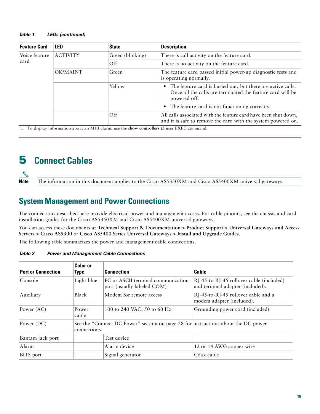
The following table summarizes the power and management cable connections.
Table 2 | Power and Management Cable Connections |
| ||
|
|
|
|
|
|
| Color or |
|
|
Port or Connection | Type | Connection | Cable | |
|
|
|
|
|
Console |
| Light blue | PC or ASCII terminal communication | |
|
|
| port (usually labeled COM) | and terminal adapter (included). |
|
|
|
|
|
Auxiliary |
| Black | Modem for remote access | |
|
|
|
| modem adapter (included). |
|
|
|
|
|
Power (AC) |
| Power | 100 to 240 VAC, 50 to 60 Hz | Grounding power cord (included). |
|
| cable |
|
|
|
|
|
|
|
Power (DC) |
| See the “Connect DC Power” section on page 28 for instructions about the DC power | ||
|
| connections. |
|
|
|
|
|
| |
Bantam jack port |
| Test device |
| |
|
|
|
|
|
Alarm |
|
| Alarm device | 12 or 14 AWG copper wire |
|
|
|
|
|
BITS port |
|
| Signal generator | Coax cable |
|
|
|
|
|
15
