Appendix A Troubleshooting
Reading the LEDs
Table | LED Summary |
10G SFP+ LED
SFP Link-Active
Orange
Off
HP
Link and Active Indicator
Not Enabled
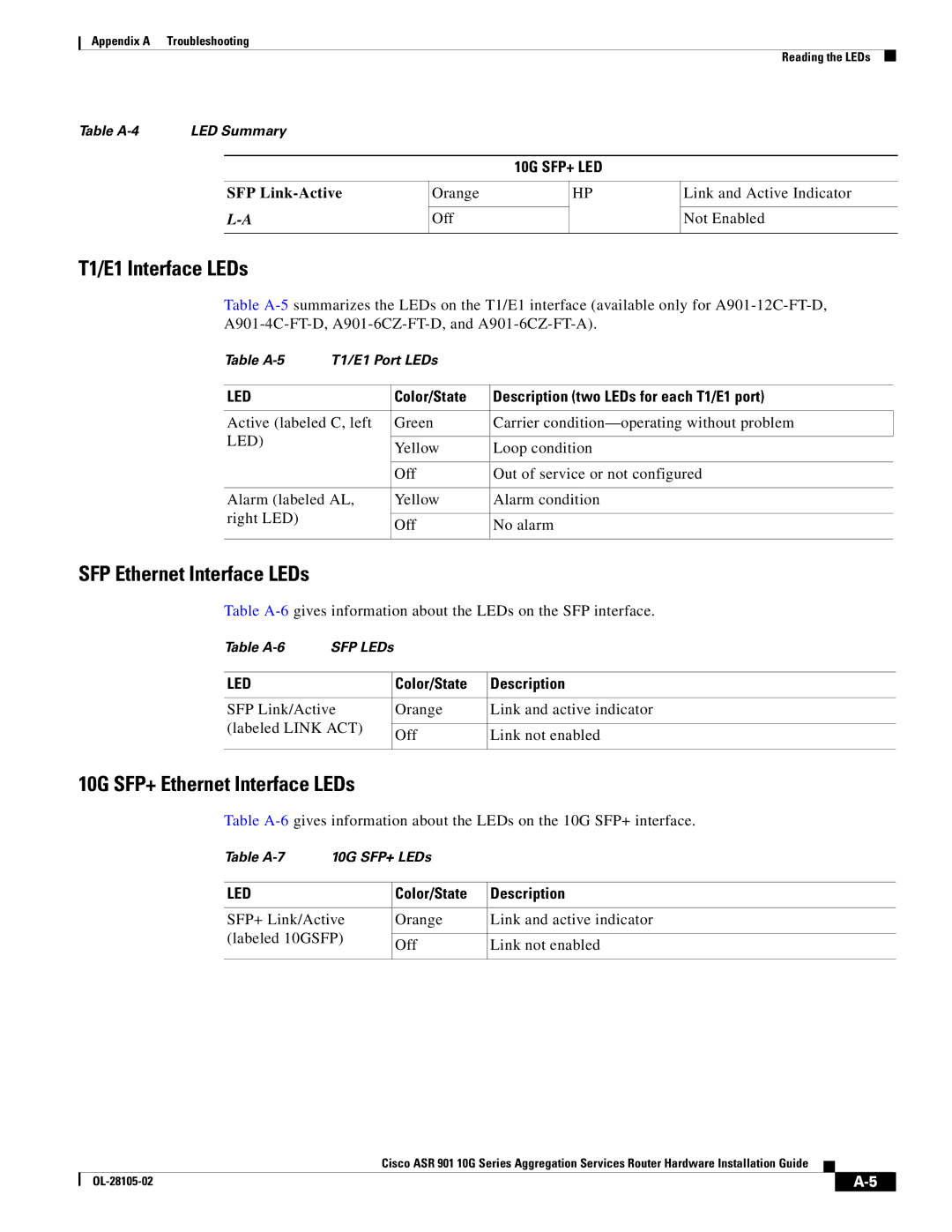
T1/E1 Interface LEDs
Table
Table | T1/E1 Port LEDs |
| |
|
|
|
|
LED |
| Color/State | Description (two LEDs for each T1/E1 port) |
|
|
| |
Active (labeled C, left | Green | Carrier | |
LED) |
|
|
|
| Yellow | Loop condition | |
|
| ||
|
|
|
|
|
| Off | Out of service or not configured |
|
|
| |
Alarm (labeled AL, | Yellow | Alarm condition | |
right LED) |
|
|
|
| Off | No alarm | |
|
| ||
|
|
|
|
SFP Ethernet Interface LEDs
Table
Table | SFP LEDs |
|
| |
|
|
|
|
|
LED |
|
| Color/State | Description |
|
|
|
| |
SFP Link/Active |
| Orange | Link and active indicator | |
(labeled LINK ACT) |
|
|
| |
| Off | Link not enabled | ||
|
|
| ||
|
|
|
|
|
10G SFP+ Ethernet Interface LEDs
Table
Table | 10G SFP+ LEDs |
| ||
|
|
|
| |
LED |
| Color/State | Description | |
|
|
| ||
SFP+ Link/Active | Orange | Link and active indicator | ||
(labeled 10GSFP) |
|
| ||
Off | Link not enabled | |||
|
| |||
|
|
|
| |
Cisco ASR 901 10G Series Aggregation Services Router Hardware Installation Guide
| ||
|