Appendix B Cable Specifications
GPS Port Pinouts
Table | Time of Day |
| |
|
|
|
|
Pin | Signal Name | Direction | Description |
|
|
|
|
3 |
|
| Not connected |
|
|
|
|
4 | Ground |
|
|
|
|
|
|
5 | Ground |
|
|
|
|
|
|
6 |
|
| Not connected |
|
|
|
|
7 | TOD_N | Output/Input | Time of Day RS422 differential input |
|
|
| or output |
|
|
|
|
8 | TOD_P | Output/Input | Time of Day RS422 differential input |
|
|
| or output |
|
|
|
|
GPS Port Pinouts
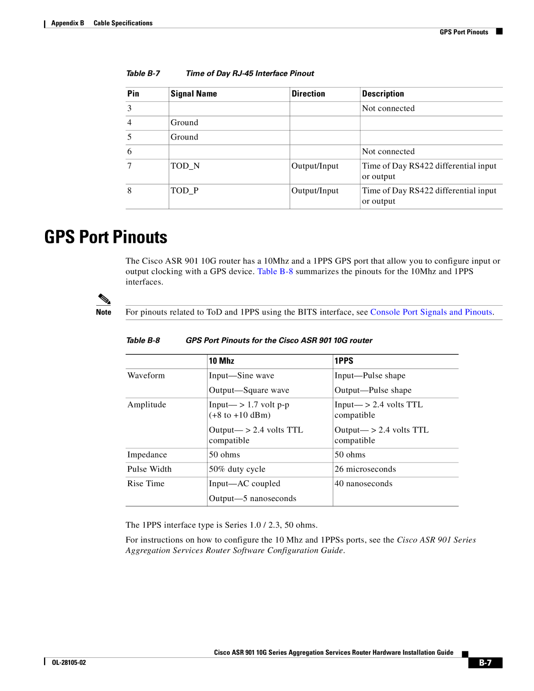
The Cisco ASR 901 10G router has a 10Mhz and a 1PPS GPS port that allow you to configure input or output clocking with a GPS device. Table
Note For pinouts related to ToD and 1PPS using the BITS interface, see Console Port Signals and Pinouts.
Table | GPS Port Pinouts for the Cisco ASR 901 10G router | ||
|
|
|
|
|
| 10 Mhz | 1PPS |
|
|
|
|
Waveform |
| ||
|
| ||
|
|
|
|
Amplitude |
| Input— > 1.7 volt | Input— > 2.4 volts TTL |
|
| (+8 to +10 dBm) | compatible |
|
| Output— > 2.4 volts TTL | Output— > 2.4 volts TTL |
|
| compatible | compatible |
|
|
|
|
Impedance |
| 50 ohms | 50 ohms |
|
|
|
|
Pulse Width |
| 50% duty cycle | 26 microseconds |
|
|
|
|
Rise Time |
| 40 nanoseconds | |
|
|
| |
|
|
|
|
The 1PPS interface type is Series 1.0 / 2.3, 50 ohms.
For instructions on how to configure the 10 Mhz and 1PPSs ports, see the Cisco ASR 901 Series Aggregation Services Router Software Configuration Guide.
Cisco ASR 901 10G Series Aggregation Services Router Hardware Installation Guide
| ||
|
