Chapter 1 | Introduction |
Hardware Description
•Two miniature coaxial connectors for 10MHZ and 1PPS timing
•A single alarm port
•A single USB port (for AC version)
•Dual feed supply with redundant DC inputs or single AC input. The following LEDs
–Ethernet ports
–SFP ports
–Chassis: Single LED for multiple conditions
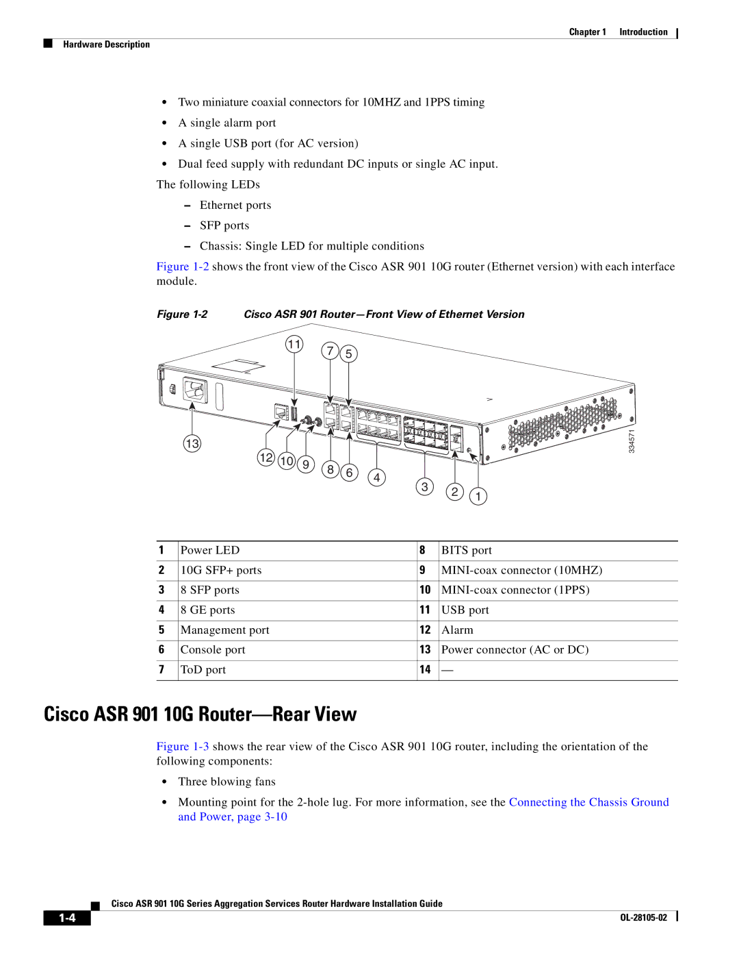
Figure 1-2 shows the front view of the Cisco ASR 901 10G router (Ethernet version) with each interface module.
Figure 1-2 Cisco ASR 901 Router—Front View of Ethernet Version
11
13
7 5
334571
12 | 10 | 9 | 8 | 6 |
|
|
| 4 | |||
|
|
| |||
|
|
|
|
|
3 2 1
1 | Power LED | 8 | BITS port | |
|
|
|
| |
2 | 10G SFP+ ports | 9 | ||
|
|
|
|
|
3 | 8 | SFP ports | 10 | |
|
|
|
|
|
4 | 8 | GE ports | 11 | USB port |
|
|
|
| |
5 | Management port | 12 | Alarm | |
|
|
|
| |
6 | Console port | 13 | Power connector (AC or DC) | |
|
|
|
| |
7 | ToD port | 14 | — | |
|
|
|
|
|
Cisco ASR 901 10G Router—Rear View
Figure 1-3 shows the rear view of the Cisco ASR 901 10G router, including the orientation of the following components:
•Three blowing fans
•Mounting point for the 2-hole lug. For more information, see the Connecting the Chassis Ground and Power, page 3-10
Cisco ASR 901 10G Series Aggregation Services Router Hardware Installation Guide
|
| |
|